Fixed ball valve

A technology of fixed ball valve and fixed shaft, which is applied in the direction of valve details, valve device, valve shell structure, etc., can solve the problems of increasing the cost of fixed ball valve, low production efficiency, complicated structural design, etc., and achieves simple structure, quick installation and easy assembly. way simple effect

Active Publication Date: 2016-12-07
JIANGSU GAOHUA FLUID CONTROL CO LTD
View PDF4 Cites 0 Cited by
  • Summary
  • Abstract
  • Description
  • Claims
  • Application Information

AI Technical Summary

Problems solved by technology

[0003] The current fixed ball valve needs to use bearings. In order to ensure its sealing performance, the structural design is complicated, and the installation is difficult and cumbersome, which greatly increases the cost of the fixed ball valve. The production efficiency is not high and the yield rate is low.

Method used


Image

  • Fixed ball valve
  • Fixed ball valve
  • Fixed ball valve

Examples


Embodiment Construction

[0018] The present invention will be further described in detail below in conjunction with the accompanying drawings and examples. The following examples are explanations of the present invention and the present invention is not limited to the following examples.

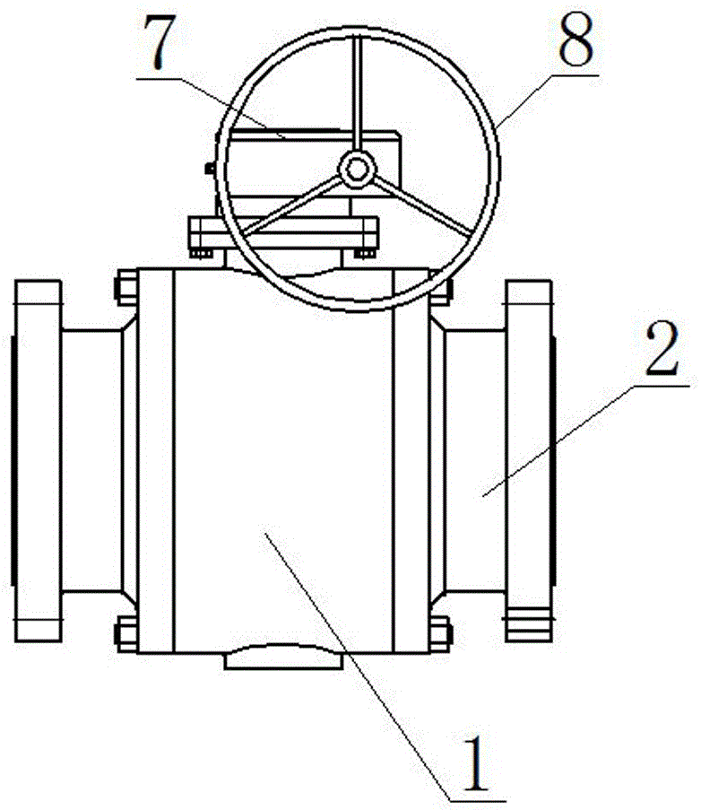
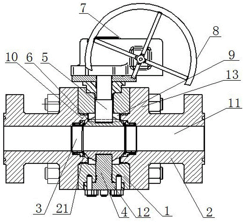
[0019] As shown in the figure, a fixed ball valve of the present invention includes a valve body 1, a connecting body 2 at both ends, a valve seat 3, a fixed shaft 4, a rotating shaft 5, a valve ball 6, a gear box 7 and a valve stem 8, and the valve body 1 There is a ball cavity matching the valve ball 6 inside, the valve ball 6 is rotated and set in the ball cavity, the lower end of the valve body 1 is opened with a fixed shaft hole matching the fixed shaft 4, the fixed shaft 4 is fixed in the fixed shaft hole, and the valve ball The lower end of 6 is rotatably set on the upper end of fixed shaft 4, and the valve body 1 is shortly opened with a rotating shaft hole matching the rotating shaft 5. The output shaft of ...


PUM


Abstract

The invention discloses a fixed ball valve. A valve ball is rotationally arranged in a ball cavity. A fixed shaft hole matched with a fixed shaft is formed in the lower end of a valve body. The fixed shaft is fixed in the fixed shaft hole. The lower end of the valve ball is rotationally arranged at the upper end of the fixed shaft. A rotary shaft is rotationally arranged in a rotary shaft hole. The lower end of the rotary shaft is fixedly connected with the upper end of the valve ball. The upper end of the rotary shaft and an output shaft of a gear case are fixed, and the rotary shaft is driven by the gear case to rotate. A valve rod is fixed to an input shaft of the gear case. A through hole is formed in the middle of the valve body in the horizontal direction. An insertion part matched with the inner diameter of the through hole of the valve body is arranged at one end of each of connectors at the two ends. Valve seats are arranged on the two sides of the valve ball. When the connectors at the two ends are inserted in and fixed to the two ends of the through hole of the valve body, the valve seats are clamped between the connectors and the valve ball, and a through through-hole pipeline is formed on the connectors at the two ends, the valve seats and the valve ball. The fixed ball valve is simple in structure and convenient to mount, the production efficiency is greatly improved, the requirement for skills of workers is low, and therefore the overall rate of finished products is increased.

Description

technical field [0001] The invention relates to a ball valve, in particular to a fixed ball valve. Background technique [0002] Fixed ball valve is a new generation of high-performance ball valve, suitable for long-distance pipelines and general industrial pipelines, its strength, safety, and resistance to harsh environments have been specially considered in design, and it is suitable for various corrosive and non-corrosive media . Compared with the floating ball valve, when it is working, the force generated by the fluid pressure in front of the valve on the ball is all transmitted to the bearing, which will not make the ball move to the valve seat, so the valve seat will not bear excessive pressure, so the fixed ball valve Small torque, small deformation of valve seat, stable sealing performance, long service life, suitable for high pressure and large diameter occasions. [0003] The current trunnion ball valve needs to use bearings. In order to ensure its sealing perfo...

Claims


Application Information

Patent Timeline
Patent Type & Authority Applications(China)
IPC IPC(8): F16K5/06F16K5/08F16K27/06F16K41/02
CPCF16K5/0647F16K5/0689F16K5/0694F16K27/067
Inventor 雅克张亮
Owner JIANGSU GAOHUA FLUID CONTROL CO LTD
Why Eureka
Try Eureka