Simple solar drying device

A simple and simple technology for solar drying, applied in the field of solar energy, can solve the problems of low solar energy utilization rate, no material turning effect, poor drying effect, etc., and achieve the effect of improving drying effect, simple structure, and good drying effect

Inactive Publication Date: 2016-12-07
成都锦汇绿源环保技术有限公司
View PDF1 Cites 8 Cited by
  • Summary
  • Abstract
  • Description
  • Claims
  • Application Information

AI Technical Summary

Problems solved by technology

[0002] Solar energy generally refers to the radiant energy of sunlight. In the case of decreasing fossil fuels, solar energy has become an important part of human energy use and has been continuously developed. The basic methods of solar energy utilization can be divided into photothermal utilization and photoelectric utilization. , photochemical utilization, and photobiological utilization. Among the four types, photothermal utilization is the most mature and widely used, and the cost is relatively low. Using solar energy to dry materials is photothermal utilization. The way of drying directly absorbs solar energy and converts it into heat, and then passes through the heat transfer between the surface of the material and the inside of the material. The traditional drying method has low utilization rate of solar energy, long drying time and poor drying effect. In order to solve the above Problem, the existing patent announcement number is CN105202874A patent discloses a drying device, but this device requires high light intensity and low practicability, and this device does not have the effect of turning material, the drying effect is poor, and it is inconvenient Discharge

Method used


Image

  • Simple solar drying device

Examples


Embodiment Construction

[0012] The following will clearly and completely describe the technical solutions in the embodiments of the present invention with reference to the accompanying drawings in the embodiments of the present invention. Obviously, the described embodiments are only some, not all, embodiments of the present invention. Based on the embodiments of the present invention, all other embodiments obtained by persons of ordinary skill in the art without making creative efforts belong to the protection scope of the present invention.

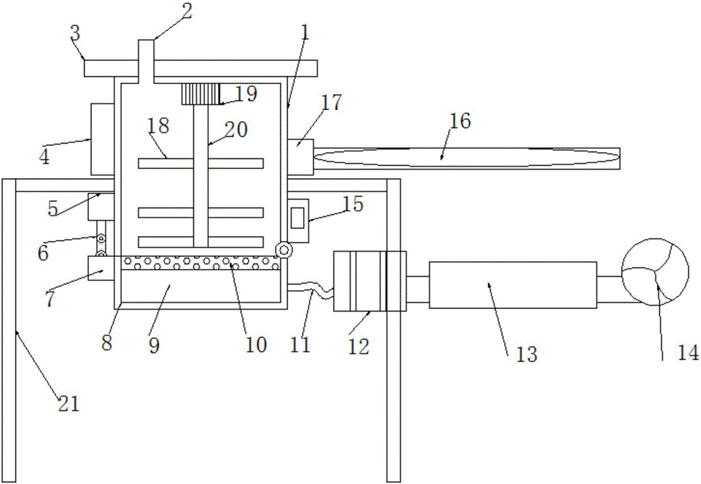
[0013] see figure 1 , in the embodiment of the present invention, a simple solar drying device includes a drying box 1 and a feeding port 2, the lower end of the drying box 1 is symmetrically provided with support legs 21 on both sides, the upper left side of the drying box 1 is provided with a battery 4, and the battery 4 It is electrically connected to the solar power generation panel 3 located on the top of the drying box 1. The solar power generation panel...


PUM


Abstract

The invention discloses a simple solar drying device. The simple solar drying device comprises a drying box and a charging port. Supporting legs are symmetrically arranged on the two sides of the lower end of the drying box. A storage battery is arranged on the upper left side of the drying box and electrically connected with a solar power generation plate located on the top of the drying box. The charging port is formed in the top of the drying box. The lower end of the drying box is rotationally provided with an overturning base plate. A connecting block is arranged at the left end of the overturning base plate. A telescopic air cylinder is further arranged on the left side face of the drying box. The output end of the telescopic air cylinder is connected with the connecting block through a connecting rod. The telescopic air cylinder is electrically connected with a control panel located on the right side of the drying box. A partition screen plate is arranged at the upper end of the overturning base plate. Ventilation holes are evenly distributed in the surface of the partition screen plate. A stirring motor is arranged on the top in the drying box and electrically connected with the control panel. A stirring shaft is arranged at the output end of the stirring motor. The simple solar drying device is simple and reasonable in structure, good in material overturning effect and drying effect and high in efficiency and practicality, and discharging is facilitated.

Description

technical field [0001] The invention relates to the technical field of solar energy, in particular to a simple solar drying device. Background technique [0002] Solar energy generally refers to the radiant energy of sunlight. In the case of decreasing fossil fuels, solar energy has become an important part of human energy use and has been continuously developed. The basic methods of solar energy utilization can be divided into photothermal utilization and photoelectric utilization. , photochemical utilization, and photobiological utilization. Among the four types, photothermal utilization is the most mature and widely used, and the cost is relatively low. Using solar energy to dry materials is photothermal utilization. The way of drying directly absorbs solar energy and converts it into heat, and then passes through the heat transfer between the surface of the material and the inside of the material. The traditional drying method has low utilization rate of solar energy, lo...

Claims


Application Information

Patent Timeline
Patent Type & Authority Applications(China)
IPC IPC(8): F26B11/14F26B25/04F26B23/10F24J2/08F24S23/30
CPCY02E10/40F26B11/14F24S23/30F26B23/10F26B25/04
Inventor 崔海保
Owner 成都锦汇绿源环保技术有限公司
Why Eureka
Try Eureka