
Microchannel heat exchanger system

A technology of microchannel heat exchanger and heat exchange system, applied in the field of microchannel heat exchanger system of non-wetting multiphase flow, can solve the problems of restricted use area, complex heat exchange system, difficult separation and recovery of multiphase fluid, etc.

Inactive Publication Date: 2016-12-07
SUZHOU NUSSELT TECH CO LTD
View PDF9 Cites 20 Cited by
  • Summary
  • Abstract
  • Description
  • Claims
  • Application Information

AI Technical Summary

Problems solved by technology

In micro-reactors or micro-heat exchangers, the inlet and outlet of microchannels are designed with shunt pipes and headers for mixing and collecting multiphase fluids. The fluid in the pipeline is driven by the pressure difference between the inlet and outlet. This design method leads to It is difficult to separate and recover multiphase fluids after flowing through microchannels. The pressure-driven method also limits its application area. The overall heat exchange system is relatively complicated, which limits its application.

Method used


Image

  • Microchannel heat exchanger system
  • Microchannel heat exchanger system
  • Microchannel heat exchanger system

Examples


Embodiment Construction

[0027] The preferred embodiments of the present invention will be described in detail below in conjunction with the accompanying drawings, so that the advantages and features of the present invention can be more easily understood by those skilled in the art, so as to define the protection scope of the present invention more clearly.

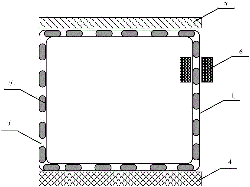
[0028] See attached figure 1 , a microchannel heat exchanger system of this embodiment, including a closed flow channel 1, the flow channel 1 is set between the cold source 5 and the heat source 4 for heat transfer, the flow channel 1 can use copper tubes, aluminum tubes , quartz tube, etc., can also be formed by etching on the silicon base; the flow channel 1 is sealed with two-phase fluid or multi-phase fluid, and the multi-phase fluid is non-wetting, which can be gas, liquid or liquid according to actual needs Metals; non-wetting multiphase fluids with flow regimes of bubbly or slug flow. When only one phase of the multiphase fluid is in dire...


PUM


Abstract

The invention relates to the field of application of microchannel heat exchangers, and particularly discloses a microchannel heat exchanger system. The microchannel heat exchanger system comprises a closed flowing channel located between a cold source and a heat source and a magnet outside the channel. Two or multiple phases of non-wetting fluid are closed in the channel. The flowing state of the multiple phases of fluid is bubble flow or slug flow. At least one phase of fluid in the multiple phases of fluid is magnetic fluid. Microchannel fluid drives the multiple phases of fluid to cyclically flow in the channel through the thermomagnetic effect of the magnetic fluid or with extra electromagnetic field force as drive force. The microchannel heat exchanger system is simple in structure; mixing and separating of multiple phases of fluid at an inlet and an outlet in conventional design are avoided; no rotary component is arranged in the system, and high reliability is achieved; and the system fully utilizes the heat transfer enhancement mechanism of heat convection of the multiple phases of non-wetting fluid in a microchannel, and the heat exchange efficiency of a microchannel heat exchanger is greatly improved.

Description

technical field [0001] The invention relates to the application field of microchannel heat exchangers, in particular to a microchannel heat exchanger system of non-wetting multiphase flow. Background technique [0002] With the wide application of micro-electro-mechanical and nano-devices in electronic biology and other fields, thermal design and thermal control of highly integrated micro-electronic devices and VLSI systems have become key issues for technological development and breakthroughs. Microchannel heat exchangers have application characteristics such as compact structure, large specific surface area, and high heat exchange efficiency. They have good application prospects in the above-mentioned chip and conventional air conditioning, refrigeration and other industries. [0003] Under micro-scale conditions, the fluid is basically in a laminar flow, and the radial mixing of the fluid only depends on molecular diffusion. For liquid fluids, this molecular diffusion is ...

Claims


Application Information

Patent Timeline
IPC IPC(8): F28D21/00
CPCF28D21/00F28D2021/0028
Inventor 沈珂珂贺群武
Owner SUZHOU NUSSELT TECH CO LTD
Learn More