
Structural member temperature rise experiment device and application method

An experimental device and a technology for structural components, applied in the field of temperature rise experimental devices for structural components, can solve the problems of not considering the spatial location characteristics of structural components, and achieve the effects of abundant experimental data, simple experimental operation and simple structure

Active Publication Date: 2016-12-07
HARBIN INST OF TECH
View PDF12 Cites 6 Cited by
  • Summary
  • Abstract
  • Description
  • Claims
  • Application Information

AI Technical Summary

Problems solved by technology

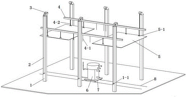
[0005] In view of the status of the prior art, the present invention provides a temperature rise experimental device for structural components and a method of use, which overcomes the problem that the prior art cannot reflect the scale of fires that may occur in different types of buildings, and does not consider the spatial location characteristics of structural components. According to the deficiencies, it is possible to carry out experimental research on the temperature rise of components with different fire source types, fire source scales, different positions and placement methods in space, different types, composition materials, and cross-sectional forms.

Method used


Image

  • Structural member temperature rise experiment device and application method
  • Structural member temperature rise experiment device and application method
  • Structural member temperature rise experiment device and application method

Examples


Embodiment 1

[0063] In the first step, two thermocouples 10 are arranged around the lower surface of the floor specimen 9 or the beam specimen 11 according to the experimental plan. There is a certain horizontal distance directly above the center line of the thermocouple 10 and the fire source device 6, and the measuring point B and the measuring point A are at the same height. Two thermocouples 10 are arranged inside the floor specimen 9 or the beam specimen 11, that is, measuring point a is located directly above measuring point A, measuring point b is located directly above measuring point B, and measuring point a and measuring point b Contour.

[0064] After the first step is completed, enter the second step to the eighth step of the method.

[0065] According to the experimental protocol, the experiment was stopped at 38 minutes after ignition. When the temperature of measuring points A and B drops below the temperature of measuring points a and b, stop temperature data collection a...


PUM


Abstract

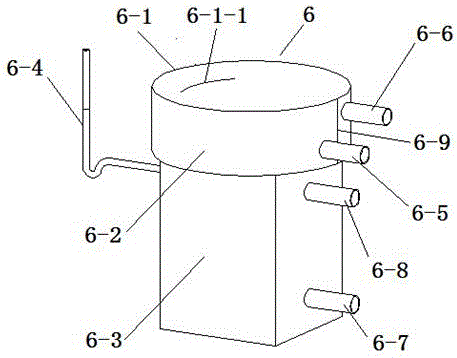
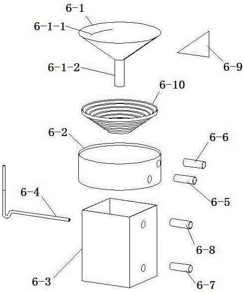
The invention relates to a structural member temperature rise experiment device and an application method. The application method comprises the steps of confirming measure points, and arranging a thermoelectric couple; lifting a test specimen to a specified height through the device, wherein a fire source device is located under the test specimen, and cooling water is at a circulating state; switching off a valve I and a water pump, switching on a valve II and an oil pump at the same time, and injecting oil fuels into a water oil transfusion box and a funnel-shaped combustor; igniting the oil fuels, starting the valve II and the oil pump at the same time, monitoring a fluid level condition of the oil fuels through a fluid level gauge, and keeping a fluid level of the oil fuels in the funnel-shaped combustor to be constant basically; when an experiment is about to finish, switching off the valve II and the oil pump, switching on the valve I and the water pump at the same time, and injecting water into the water oil transfusion box until the oil fuels are burned out, wherein after the experiment is finished, a temperature data acquisition device is used for storing time-temperature data of each measuring point. The structural member temperature rise experiment device is simple in structure, flexible in component arrangement, high in integral security, simple and convenient to experimentally operate, good in reutilization, high in applicability for the experiment test specimen, and rich in acquired experimental data.

Description

technical field [0001] The invention relates to the field of civil engineering, in particular to a structural member temperature rise experimental device and a use method for the structural member temperature rise experimental research. Background technique [0002] The collapse of building structures under the fire has caused huge losses to the lives and properties of the people. When a fire occurs, the internal temperature of the structural components will continue to rise due to the radiation heat transfer of the fire source and the radiation heat transfer and convective heat transfer of the high-temperature smoke, and the mechanical properties of their own materials will continue to deteriorate. When the resistance of the structure is insufficient to resist the external load, the collapse of the overall building structure occurs. The main factors affecting the above process include: the size of the actual building fire scale and the internal environment of the building,...

Claims


Application Information

Patent Timeline
Patent Type & Authority Applications(China)
IPC IPC(8): G01N25/32
CPCG01N25/32
Inventor 倪照鹏尹亮范峰崔海浩彭磊马会环黄鑫原志红
Owner HARBIN INST OF TECH
Learn More