TOFD near surface dead zone defect locating detection method based on wave-type transformation

A technology of positioning detection and detection method, which is applied to measurement devices, analysis of solids using sonic/ultrasonic/infrasonic waves, and material analysis using sonic/ultrasonic/infrasonic waves, etc. problems, to achieve the effect of strong applicability, reduction of near-surface blind spots, and high precision

Inactive Publication Date: 2016-12-07
DALIAN UNIV OF TECH
View PDF4 Cites 6 Cited by
  • Summary
  • Abstract
  • Description
  • Claims
  • Application Information

AI Technical Summary

Problems solved by technology

The parameter optimization method improves the longitudinal resolution of near-surface defects by adjusting parameters such as probe frequency, angle, and probe center distance, and realizes the positioning of near-surface defects. This method can reduce the near-surface blind area to about 4 mm; the TOFD image signal processing method is as follows: Filtering, spectrum analysis, Hilbert transform and other methods, by decomposing and reconstructing the extracted original A-scan signal to calculate the defect position, the blind area can be reduced to 3mm, the limitation is that the parameter selection and operation are more complicated; TOFDW method It is a secondary wave detection method, which uses the bottom surface echo to detect defects. The energy of the sound wave is relatively weak, and after the bottom surface reflection, the received A-scan signal is more complicated. At this time, the blind zone range is about 2mm

Method used


Image

  • TOFD near surface dead zone defect locating detection method based on wave-type transformation
  • TOFD near surface dead zone defect locating detection method based on wave-type transformation
  • TOFD near surface dead zone defect locating detection method based on wave-type transformation

Examples


Embodiment Construction

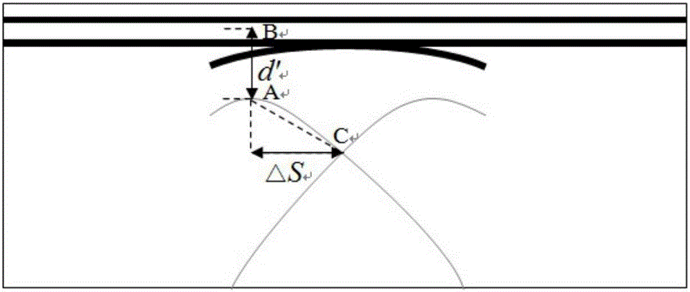
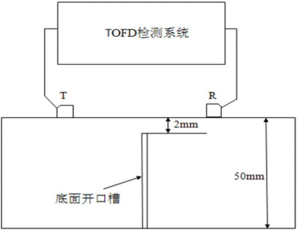
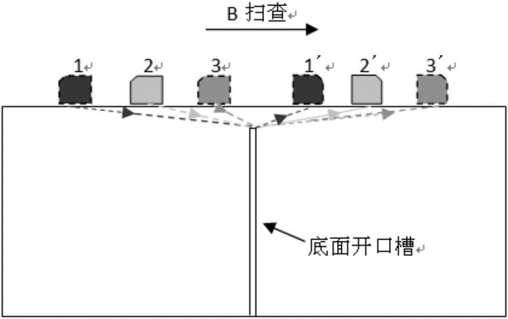
[0016] figure 1 Schematic diagram of deformation wave location in B-scan images. In the quantitative detection method of near-surface defects based on deformation wave, the ultrasonic testing system used is as follows: figure 2 As shown, it includes a TOFD ultrasonic detector, a pair of TOFD probes with a nominal frequency of 10MHz, a pair of longitudinal wave wedges with a deflection angle of 60°, and a scanning device.

[0017] Next, the method of the present invention is verified by using a carbon steel test block provided with an open groove on the bottom as the test object. The specific verification process and results are as follows:

[0018] The test object is a carbon steel test block, the thickness of the carbon steel test block is 50.00mm, and the sound velocity of longitudinal wave of the material is 5.90km / s. The bottom open groove is 2.00mm deep from the detection surface. A TOFD ultrasonic detector is used, and a pair of TOFD probes and wedges with a probe n...


PUM

PropertyMeasurementUnit
thicknessaaaaaaaaaa

Abstract

The invention discloses a TOFD near surface dead zone defect locating detection method based on wave-type transformation and belongs to the field of nondestructive detection. The method includes that an ultrasonic detection system comprising a TOFD ultrasonic detector, a detection probe, a calibration block and scanning device is adopted for TOFD detection; longitudinal waves emitted by the TOFD probe diffract when encountering defects, and when an incident angle reaches a supercritical value, wave-type transformation of longitudinal wave to transverse wave or transverse wave to longitudinal wave occurs; a defect end point solution model is built according to geometrical relationship among sonic path distances of waves different in type in a scanning image B; a projection distance d' of shortest sonic path distance of transformed waves in the vertical direction and a projection distance S in the horizontal direction between an intersection point of the transformed waves and a shortest sonic path distance position are measured, and then a distance d between a defect end point and a detection face can be calculated by combining the projection distance d' and the projection distance S with a probe central distance 2S, longitudinal wave sonic speed C1 and transverse wave sonic speed Cs through a formula to realize locating of near surface dead zone defects. By the method, original A scanning signals do not need to be extracted for analysis and post-processing; the method is high in operability and high in engineering application value.

Description

technical field [0001] The invention relates to a method for locating and detecting defects in a near-surface blind zone of TOFD based on wave-type conversion, and belongs to the field of non-destructive testing. Background technique [0002] Time of Flight Diffraction (TOFD) is a non-destructive testing technique that accurately measures the size and depth of defects. This technology is based on the Huygens principle, and uses the diffraction wave generated when the emitted longitudinal wave encounters a defect to quantify and locate the defect. This technology quantifies defects according to the time difference of diffracted waves, which has small error, high defect detection rate, and is simple and fast. However, in TOFD inspection, the diffracted waves of defects close to the detection surface are likely to be aliased with the through waves, forming a near-surface blind area, which makes it difficult to locate defects. [0003] At present, the methods to suppress TOFD ...

Claims


Application Information

Patent Timeline
Patent Type & Authority Applications(China)
IPC IPC(8): G01N29/06G01N29/07
CPCG01N29/069G01N29/07G01N2291/0234G01N2291/0421G01N2291/0422
Inventor 金士杰康达丁宁林莉
Owner DALIAN UNIV OF TECH
Why Eureka
Try Eureka