Distributed sensing fiber sound emission fusion perception system and running method

A sensing fiber and sensing system technology, applied in the field of distributed sensing fiber optic acoustic emission fusion sensing system, can solve the problems of poor resistance to electrical interference, large system, too many cables, etc., to reduce monitoring costs, high Spatial resolution, simple effect of structure layout

Active Publication Date: 2016-12-07
HOHAI UNIV
View PDF7 Cites 7 Cited by
  • Summary
  • Abstract
  • Description
  • Claims
  • Application Information

AI Technical Summary

Problems solved by technology

[0004] However, due to the diversification of performance parameters and high standard requirements of the currently developed monitoring equipment, the actual application of optical fiber sensing technology is still far behind the current demand for this technology. Among them, the fusion of sensing optical fiber technology and acoustic emission technology is It is one of the areas where the research is extremely lacking. Since the sensing fiber optic technology and the acoustic emission technology have excellent monitoring and detection performance, their integration will inevitably produce major technological innovations, and it is necessary to break through the huge system, too many cables, and the resistance to electrical testing. Piezoelectric Ceramic Acoustic Emission Detection Method with Poor Interference Ability and Current Point Monitoring Fiber Bragg Grating Type Acoustic Emission Detection System

Method used


Image

  • Distributed sensing fiber sound emission fusion perception system and running method
  • Distributed sensing fiber sound emission fusion perception system and running method
  • Distributed sensing fiber sound emission fusion perception system and running method

Examples


Embodiment Construction

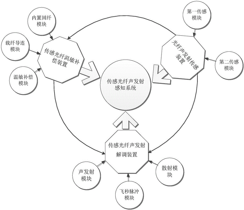
[0031] Such as Figure 1 to Figure 8 As shown, a distributed sensing optical fiber acoustic emission fusion sensing system of the present invention includes a sensing optical fiber temperature-sensitive compensation device and a sensing optical fiber acoustic emission demodulation device, and the sensing optical fiber in the sensing optical fiber temperature-sensitive compensation device passes through After compensation, it enters into the sensing optical fiber acoustic emission demodulation device.

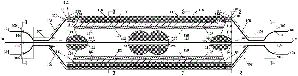
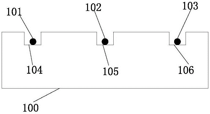
[0032] A sensor optical fiber temperature-sensitive compensation packaging device of the present invention includes a fiber-carrying guide connection module, a built-in fixed fiber module, and a temperature-sensitive compensation module. The fiber carrying and connecting module includes an optical fiber holding platform 100 with a length of 20 cm, a width of 10 cm, and a height of 5 cm, an upper fiber slot 104 with a slot depth of 2 cm, a middle fiber slot 105 with a slot depth ...


PUM


Abstract

The invention discloses a distributed sensing fiber sound emission fusion perception system and a running method. The perception system comprises a sensing fiber temperature-sensitive compensation device and a sensing fiber sound emission demodulation device, wherein a sensing fiber in the sensing fiber temperature-sensitive compensation device is compensated, and enters the sensing fiber sound emission demodulation device. By adopting the fusion perception system, pure overlapping of the conventional simple technologies is broken through on the aspects of mechanism and practical engineering application; a femtosecond laser optical frequency comb technology is introduced and fused with a sound emission technology, and Rayleigh ejection scattering and Brillouin scattering are separated, so that sound emission waves are perceived in a grading way; a multi-device multi-module and multi-component fusion system consisting of the sensing fiber temperature-sensitive compensation device and the optical fiber sound emission demodulation device has the advantages of spatial positioning, whole-process distribution, high spatial resolution, high detection accuracy, quantitative detection and the like, and has great advantages on the aspects of lowering the monitoring cost, increasing the monitoring accuracy, improving the engineering practical performance, and the like.

Description

technical field [0001] The invention relates to a distributed sensing optical fiber acoustic emission fusion sensing system and an operating method, belonging to the field of safety monitoring and detection of water engineering structures. Background technique [0002] Due to the invention of laser and optical fiber, optical fiber technology has achieved world-renowned success. Driven by optical communication technology, the research and development of various optical fibers, devices, components, instruments and mechanical devices have made great progress. As we all know, light wave is a kind of electromagnetic wave. When the electromagnetic wave is incident into a medium such as an optical fiber, the incident electromagnetic wave will interact with the molecules or atoms that make up the material, thereby generating a scattering spectrum. The common ones are Rayleigh scattering and Brillouin scattering. Scattering, by using the scattered light information, people have devel...

Claims


Application Information

Patent Timeline
Patent Type & Authority Applications(China)
IPC IPC(8): G01N29/14G01N29/22G01N29/32G01H9/00
CPCG01H9/004G01N29/14G01N29/223G01N29/32G01N2291/023G01N2291/0289G01N2291/106
Inventor 苏怀智杨孟顾冲时
Owner HOHAI UNIV
Why Eureka
Try Eureka