ANSYS CFX-based simulation method for radial temperature field of overhead line

A simulation method and radial temperature technology, which are applied in design optimization/simulation, special data processing applications, instruments, etc., can solve the problems of not considering the influence of radial heat transfer of conductors, unfavorable 3D sag model establishment, etc. The effect of fast calculation speed

Active Publication Date: 2016-12-07
SOUTH CHINA UNIV OF TECH
View PDF4 Cites 12 Cited by
  • Summary
  • Abstract
  • Description
  • Claims
  • Application Information

AI Technical Summary

Problems solved by technology

The radial temperature distribution calculated by this method does not take into account the influence of the air gap between the wires on the radial heat tr

Method used


Image

  • ANSYS CFX-based simulation method for radial temperature field of overhead line
  • ANSYS CFX-based simulation method for radial temperature field of overhead line
  • ANSYS CFX-based simulation method for radial temperature field of overhead line

Examples


Embodiment 1

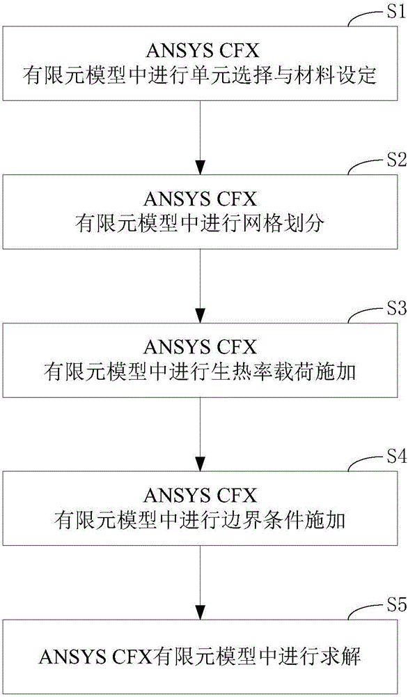
[0048] See figure 1 , figure 1 It is a flow chart of an ANSYS CFX-based simulation method for the radial temperature field of overhead wires disclosed in the present invention. figure 1 An overhead line radial temperature field simulation method based on ANSYS CFX is shown, which specifically includes the following steps:

[0049] S1. Element selection and material setting in the ANSYS CFX finite element model;

[0050] In a specific application, the step S1 is specifically:

[0051] Build the model according to the actual physical structure of the steel-cored aluminum strand. When setting the material, the steel core, aluminum core and air use the corresponding materials in the ANSYS CFX model material library. The core and aluminum core are solved as a solid domain, and the remaining air is solved as a fluid domain.

[0052] S2. Grid division in ANSYS CFX finite element model;

[0053] In a specific application, the step S2 is specifically:

[0054] When dividing the g...

Embodiment 2

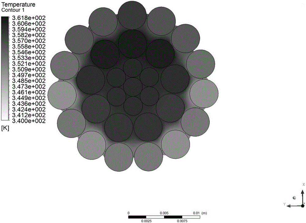
[0082] The model used in this embodiment is the LGJ 300 / 40 type wire, which is simulated in combination with an ANSYSCFX-based overhead wire radial temperature field simulation method disclosed in the present invention, and the specific steps are as follows:

[0083] S1. Element selection and material setting in the ANSYS CFX finite element model;

[0084] The LGJ 300 / 40 type wire is selected, and its 2D cross-sectional view is composed of four layers. From the inside to the outside, it is a steel core with a center radius of 1.33mm, and the center of the circle is evenly distributed on a circle with a radius of 2.66mm. Six steel cores of 1.33mm, the centers of which are evenly distributed on a circle with a radius of 5.985mm Nine aluminum cores with a radius of 1.995mm, and the centers of which are evenly distributed on a circle with a radius of 9.975mm aluminum core. On the basis of the existing wire model, an air layer with a radius of 0.2 meters is added outside. Since A...


PUM

PropertyMeasurementUnit
Radiusaaaaaaaaaa

Abstract

The invention discloses an ANSYS CFX-based simulation method for a radial temperature field of an overhead line. The method comprises the following steps of S1, performing unit selection and material setting in an ANSYS CFX finite element model; S2, performing mesh division in the ANSYS CFX finite element model; S3, performing heat generation rate load application in the ANSYS CFX finite element model; S4, performing boundary condition application in the ANSYS CFX finite element model; and S5, performing solving in the ANSYS CFX finite element model. According to the method, the radial temperature distribution field of a lead wire under different current-carrying capacities is obtained by using ANSYS CFX, and the situation that the temperature difference between the surface layer temperature and the steel core layer temperature of an aluminum cable steel reinforced type lead wire is changed with a current is obtained through a high-current experimental method; relative errors are all within 5%; and therefore, the method is of relatively strong reference significance on a radial thermal field distribution method for stranded wires.

Description

technical field [0001] The invention relates to the technical field of high voltage and insulation technology, in particular to a method for simulating the radial temperature field of overhead wires based on ANSYS CFX. Background technique [0002] With the rapid development of the economy, the electricity consumption has also increased rapidly, which has promoted the construction of the power grid. However, in the current situation, the transmission corridor still limits the construction and development of the power grid to a certain extent. The construction of new transmission corridors requires a lot of money and time, and will not alleviate the shortage of transmission corridors in the short term. Therefore, how to make full use of the power transmission capacity of the existing lines has become a problem of practical significance. [0003] At present, the mainstream technology of transmission line capacity expansion includes static capacity expansion technology, that ...

Claims


Application Information

Patent Timeline
IPC IPC(8): G06F17/50
CPCG06F30/23G06F30/367
Inventor 刘刚李炀陈垣于金雨
Owner SOUTH CHINA UNIV OF TECH
Why Eureka
Try Eureka