Reactor control rod drive mechanism
A driving mechanism and control rod technology, applied in the control of nuclear reactions, reactors, reducing greenhouse gases, etc., can solve the problems of buffer shaft fracture failure, complex structure, assembly quality affecting the service life of the control rod driving mechanism, etc., to ensure accuracy and the effect of effectiveness
- Summary
- Abstract
- Description
- Claims
- Application Information
AI Technical Summary
Problems solved by technology
Method used
Image

Examples
Embodiment 1
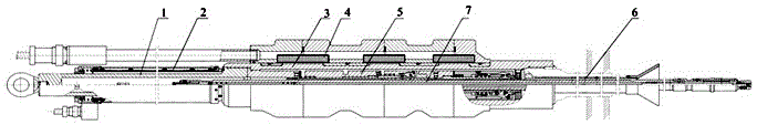
[0038] Such as Figure 1 to Figure 6 As shown, the reactor control rod driving mechanism includes a sealed casing assembly 3, a travel sleeve 1 fixedly connected to the sealed casing assembly 3, a coil assembly 4 set on the sealed casing assembly 3, and a claw set in the pressure casing assembly Component 5, the sealing shell component 3 includes a sealing shell and a tube base, and the sealing shell and the tube base are in an integrated structure.
[0039] Specifically, in the prior art, the sealing shell assembly 3 in the control rod driving mechanism only includes the sealing shell, that is, the tube base is independent of the control rod driving mechanism, and the tube base is welded to the pressure vessel when the pressure vessel is manufactured, so in During the installation of the control rod drive mechanism, welding personnel need to complete the welding of the pipe seat and the sealing shell at the installation site. Moreover, in the prior art, the sealing shell and...
Embodiment 2
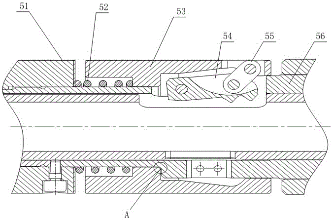
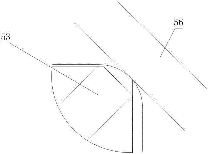
[0042] Such as Figure 1 to Figure 6 As shown, this embodiment is further limited on the basis of Embodiment 1: as a specific implementation of the hook assembly 5, the hook assembly 5 includes a buffer shaft 56 and a moving armature 53, and the buffer shaft 56 and the moving armature 53 are cylindrical structures, the shape of the buffer shaft 56 is a stepped shaft, the inner hole of the moving armature 53 is a step hole, the moving armature 53 is sleeved on the outside of the buffer shaft 56, and the outside of the buffer shaft 56 The reducing section of the moving armature 53 and the reducing section in the inner hole of the moving armature 53 are in a positive relationship. When the buffer shaft 56 and the moving armature 53 are in relative motion, the above two reducing sections contact each other to limit the buffer shaft 56 and the moving armature 53. The relative position of the buffer shaft 56 is connected with the smaller diameter end of the buffer shaft 56 through r...
Embodiment 3
[0052] The present embodiment is further limited on the basis of the technical solution provided in embodiment 1: as Figure 1 to Figure 6 As shown, the coil assembly 4 includes an inner skeleton 41 and an outer shell 42 both in a cylindrical structure, and an annular cavity for accommodating the coil winding 43 is formed between the outer shell 42 and the inner skeleton 41, and the inner The skeleton 41 is located in the inner hole of the outer casing 42;
[0053] The inner frame 41 and the outer shell 42 both include a main body made of metal and a cut-off groove 45 arranged on the main body. On the rear end face, the cut-off groove 45 on the outer shell 42 runs through the inner and outer walls and the front and rear end faces of the outer shell 42 .
[0054] In this scheme, the inner frame 41 and the outer shell 42 are metal main parts and the flow break groove 45 provided on the main body constitutes the cylindrical structure of the inner frame 41 and the outer shell 42,...
PUM
 Abstract
Description
Claims
Application Information