Automatic arranging machine for capacitors

A discharger and capacitor technology, applied in capacitors, capacitor manufacturing, circuits, etc., can solve the problems of unfavorable automatic production of capacitors, high labor costs, affecting capacitor performance, etc., to improve automatic production efficiency, reduce production costs, and improve discharge. The effect of material efficiency

Active Publication Date: 2016-12-07
广东南方宏明电子科技股份有限公司
View PDF7 Cites 3 Cited by
  • Summary
  • Abstract
  • Description
  • Claims
  • Application Information

AI Technical Summary

Problems solved by technology

Using this method, the speed of plate arrangement is slow, time-consuming, and the production efficiency is low, which is not conducive to the automatic production of capacitors. At the same time, the amount of manual labor is large, resulting in high labor costs, which is not conducive to the improvement of the economic benefits of the enterprise.
And because of working in a hot press room, especially in the hot summer working environment, the manual arrangement is to place the capacitor directly on the curing plate by human hands. During this process, the human hand directly touches the capacitor, so hand sweat will affect the capacitance. performance, resulting in quality hazards

Method used


Image

  • Automatic arranging machine for capacitors
  • Automatic arranging machine for capacitors
  • Automatic arranging machine for capacitors

Examples


Embodiment Construction

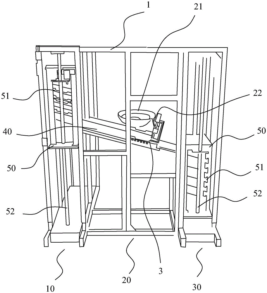
[0023] First, please refer to figure 1 and figure 2 As shown, a capacitor automatic discharge machine includes a frame 1, and a tray supply mechanism 10 located on the frame 1, a capacitor discharge mechanism 20, a tray unloading mechanism 30, and a moving motor controlled by a stepping motor. Transmission track 40, the transmission direction of the transmission track 40 is obliquely downward, the tray supply mechanism 10 and the tray blanking mechanism 30 are respectively arranged at the upper and lower ends of the delivery track 40, and the capacitor discharge mechanism 20 is set At the middle position of the conveying track 40, the tray 3 on the tray supply mechanism 10 is transferred to the capacitor discharge mechanism 20 through the transfer rail 40, and the tray 3 after the material has been discharged on the capacitor discharge mechanism 20 is passed through the conveyor. The track 40 is transferred to the tray unloading mechanism 30 . By making the transmission dir...


PUM


Abstract

The invention provides an automatic arranging machine for capacitors. The automatic arranging machine comprises a rack, a tray supply mechanism, a capacitor arranging mechanism and a tray discharge mechanism, wherein the tray supply mechanism, the capacitor arranging mechanism and the tray discharge mechanism are arranged on the rack; a tray on the tray supply mechanism is transferred to the capacitor arranging mechanism through a transfer rail; the arranged tray on the capacitor arranging mechanism is transferred to the tray discharge mechanism through the transfer rail; the capacitor arranging mechanism comprises a vibrating tray and an arranging device arranged above the transfer rail; the arranging device is provided with a trough which is vertical to the conveying direction of the transfer rail; the trough is provided with a downward opening or closing opening; the vibrating tray is connected with the trough through an arranging rail; and after the trough is full, the opening or closing opening is opened and the capacitors which are arranged in a whole row fall into the tray. By the automatic arranging machine for the capacitors, the manual labor can be reduced; a potential quality hazard due to direct contact with the capacitors by a hand is avoided; meanwhile, the automatic production efficiency of the capacitors is also improved; the production cost is reduced; and the economic benefits of enterprises are improved.

Description

technical field [0001] The invention relates to the technology in the field of capacitor production equipment, in particular to a capacitor automatic discharger that can greatly improve production efficiency. Background technique [0002] Capacitors are one of the electronic components widely used in electronic equipment, and are widely used in DC blocking, coupling, bypass, filtering, tuning loops, energy conversion, control circuits, etc. Although there are many kinds of capacitors, their basic structure and principle are the same. The common ones are electrolytic capacitors and ceramic capacitors. Among them, ceramic capacitors need to be sintered and solidified at high temperature during the production process. Before curing, the capacitors need to be evenly arranged in the On the curing tray, at present, the manual arrangement is mainly used when arranging. In this way, the disk arrangement is slow, time-consuming, and the production efficiency is low, which is not con...

Claims


Application Information

Patent Timeline
Patent Type & Authority Applications(China)
IPC IPC(8): H01G13/00B65G47/26
CPCB65G47/26B65G47/30H01G13/00
Inventor 罗世勇赵俊斌施砚馨黄泰霖罗致成
Owner 广东南方宏明电子科技股份有限公司
Why Eureka
Try Eureka