
High-power hybrid type direct current circuit breaker

A DC circuit breaker, hybrid technology, applied in circuit devices, emergency protection circuit devices for limiting overcurrent/overvoltage, emergency protection circuit devices, etc., can solve long insulation recovery time, reduce service life, reliable operation Reduce the number of times and other problems to achieve the effect of fast insulation recovery time and fast energy transfer

Active Publication Date: 2016-12-07
INST OF PLASMA PHYSICS CHINESE ACAD OF SCI
View PDF6 Cites 15 Cited by
  • Summary
  • Abstract
  • Description
  • Claims
  • Application Information

AI Technical Summary

Problems solved by technology

[0005] 1. In the case of breaking a large current, the mechanical circuit breaker has a longer insulation recovery time due to the high current arc extinguishing problem, and at the same time reduces the number of reliable actions. The faster insulation recovery time is an important indicator of power system protection, and the number of reliable actions Reduction reduces its service life
[0006] 2. Due to the increase of the reverse recovery voltage of the solid-state circuit breaker, the number of series connection of power electronic devices must be increased, while the lower arc voltage of the mechanical circuit breaker during commutation is not enough to effectively conduct the series branch of the power electronic device

Method used


Image

  • High-power hybrid type direct current circuit breaker
  • High-power hybrid type direct current circuit breaker
  • High-power hybrid type direct current circuit breaker

Examples


Embodiment Construction

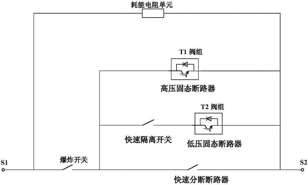
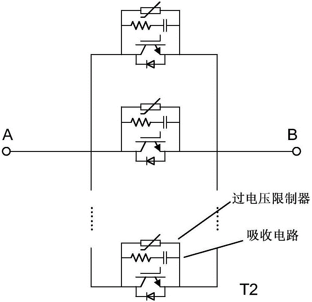
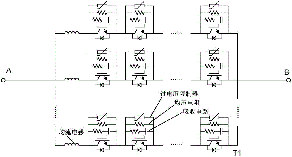
[0022] see figure 1 , 2 3. A high-power hybrid DC circuit breaker, including a mechanical circuit breaker, a solid state circuit breaker, an explosion switch and an energy dissipation resistor, the mechanical circuit breaker includes a quick breaking circuit breaker and a quick isolating switch, and the solid state circuit breaker includes a low voltage Solid-state circuit breaker and high-voltage solid-state circuit breaker; fast disconnecting switch and low-voltage solid-state circuit breaker are connected in series to form the first-stage current transfer branch, and high-voltage solid-state circuit breaker constitutes the second-stage current transfer branch. The primary current transfer branch is connected in parallel to form the main protection switch unit, then connected in series with the backup protection unit formed by the explosion switch, and finally connected in parallel with the energy dissipation branch formed by the energy dissipation resistance unit.

[0023]...


PUM


Abstract

The invention discloses a high-power hybrid type direct current circuit breaker. The high-power hybrid type direct current circuit breaker comprises a mechanical circuit breaker, a solid-state circuit breaker, an explosion switch and an energy dissipation resistor, wherein the mechanical circuit breaker comprises a rapid breaking circuit breaker and a rapid isolation switch; the solid-state circuit breaker comprises a low-voltage solid-state circuit breaker and a high-voltage solid-state circuit breaker; the rapid isolation switch is connected with the low-voltage solid-state circuit breaker in series to form a first-stage current transfer branch; the high-voltage solid-state circuit breaker forms a second-stage current transfer branch; and the rapid breaking circuit breaker is connected with the first-stage current transfer branch and the second-stage current transfer branch in parallel separately to form a main protection switch unit, then is connected with a backup protection unit which is formed by the explosion switch in series, and finally is connected with an energy dissipation branch which is formed by an energy consumption resistor unit in parallel. The high-power hybrid type direct current circuit breaker has a high-power and high-capacity direct current breaking capability, simple control and high system reliability, and can be applied to the fields of a quench protection switch of a superconducting magnet system or a direct current circuit breaker in a direct current power transmission and distribution network, and the like.

Description

technical field [0001] The invention relates to the field of DC circuit breakers, in particular to a high-power hybrid DC circuit breaker. Background technique [0002] With the rapid development of national economy and science and technology, the parameters and capacity requirements of high-power DC power supply systems are getting higher and higher, such as the rapidly developing DC transmission system, rail transit, superconducting energy storage magnets and other fields. These DC power supply systems and their special loads will bring immeasurable economic losses and social impacts if they fail to be protected in time, and the high-power new hybrid DC circuit breaker system of the present invention is to realize the above-mentioned DC power supply system and its Key equipment for special load protection. [0003] Traditional mechanical DC circuit breakers have the advantages of low on-state impedance, low loss, and strong voltage resistance, but also have the disadvanta...

Claims


Application Information

Patent Timeline
IPC IPC(8): H02H3/087H02H3/05H02H9/02
CPCH02H3/05H02H3/087H02H9/02
Inventor 傅鹏汪舒生宋执权李华卢应峣
Owner INST OF PLASMA PHYSICS CHINESE ACAD OF SCI
Learn More