Liquid-cooled motor shell

A technology of liquid-cooled motors and housings, which is applied in the direction of casings/covers/supports, electrical components, electromechanical devices, etc., which can solve the problems of small convective heat transfer coefficient, large boundary layer thickness, poor heat dissipation effect, etc., and achieve pressure Small loss, short flow path length, reduced thermal resistance and temperature rise

Inactive Publication Date: 2016-12-07
PHASE MOTION CONTROL NINGBO
View PDF8 Cites 13 Cited by
  • Summary
  • Abstract
  • Description
  • Claims
  • Application Information

AI Technical Summary

Problems solved by technology

Due to the high viscosity of hydraulic oil, it is mostly laminar flow in the flow channel of the motor, the thickness of the boundary layer is very large, the convective heat transfer coefficient of the wall surface of the flow channel is small, and the thermal resistance is large, so

Method used


Image

  • Liquid-cooled motor shell
  • Liquid-cooled motor shell
  • Liquid-cooled motor shell

Examples


Embodiment 1

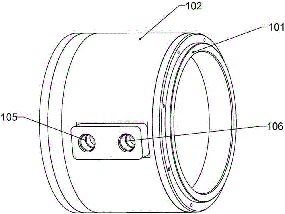
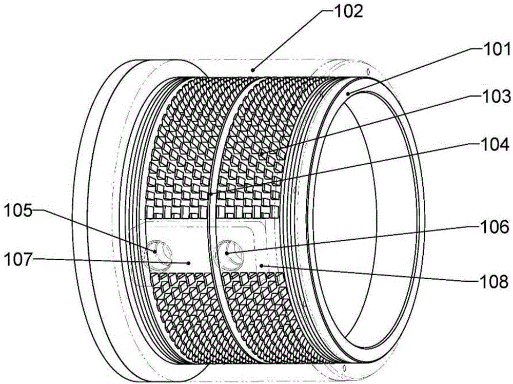
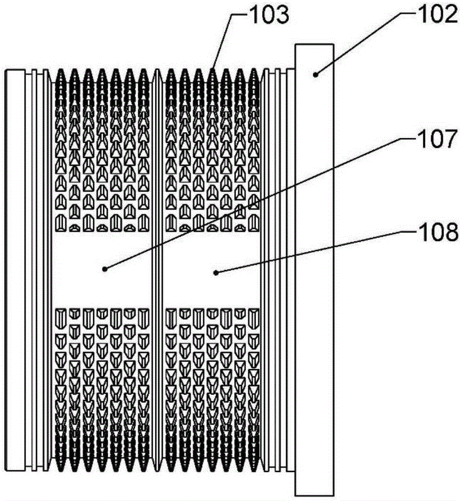
[0027] Such as figure 1 As shown in -8, a liquid-cooled motor casing includes an inner casing 101 and an outer casing 102, and the outer casing 102 is sleeved outside the inner casing 101, wherein the outer casing 102 is provided with a water inlet 105 and Water outlet 106, on the inner shell 101, corresponding to the water inlet 105 and the water outlet 106, there are respectively provided with an inlet part flow channel confluence area 107 and an outlet part flow channel confluence area 108, and the inner shell 101 is on the axis There is a turning and converging area 109 for the cooling liquid, and several rows of isolation ribs 104 are provided on the inner casing 101 for controlling the flow direction. The converging area 107, On both sides of the flow channel confluence area 108 and the flow channel turning confluence area 109 at the exit site, between the inner shell 101 and the outer shell 102, there are zigzag ribs 103, and the zigzag ribs 103 are arranged on the inne...


PUM


Abstract

The invention relates to a liquid-cooled motor shell, which comprises an inner shell and an outer shell, wherein the outer shell sleeves the outside of the inner shell; the outer shell is provided with a water inlet and a water outlet; an inlet part runner convergence zone and an outlet part runner convergence zone are arranged at the positions, corresponding to the water inlet and the water outlet, of the inner shell respectively; a runner turning convergence zone is arranged on the inner shell for dispersing and converging a cooling liquid; multiple rows of isolating ribs are arranged on the inner shell for controlling the flow direction; sawtooth fins are arranged at two sides of the inlet part runner convergence zone, the outlet part runner convergence zone and the runner turning convergence zone and between the inner shell and the outer shell, and are arranged on the inner shell or the outer shell; and the sawtooth fins are multiple rows of individual fins. By the liquid-cooled motor shell, turbulent flow can be strengthened and the thermal resistance and a temperature rise of the motor shell are obviously reduced.

Description

technical field [0001] The invention belongs to the technical field of motors, in particular to a liquid-cooled motor casing. Background technique [0002] In the development of the motor, the design of the cooling system is directly related to the temperature rise and performance of the permanent magnet motor, and needs to be paid attention to. With the increase of motor power, the temperature rise of the motor is getting higher and higher, and the requirements for the cooling system are also getting higher and higher. At the same time, in many cases, it is necessary to use hydraulic oil or the like as a cooling medium. Due to the high viscosity of the hydraulic oil, it is mostly laminar flow in the flow channel of the motor, the thickness of the boundary layer is very large, the convective heat transfer coefficient of the wall surface of the flow channel is small, and the thermal resistance is large, so the heat dissipation effect is very poor. Due to the large thermal r...

Claims


Application Information

Patent Timeline
IPC IPC(8): H02K5/18H02K5/20H02K9/19
CPCH02K5/18H02K5/20H02K9/19
Inventor 杨东升王志斌王浩朱法龙
Owner PHASE MOTION CONTROL NINGBO
Why Eureka
Try Eureka