PFC circuit, PFC control circuit and switch power source
A control circuit and circuit technology, which is applied in high-efficiency power electronic conversion, electrical components, energy industry, etc., can solve problems such as complex control circuit structure, and achieve the effect of simple circuit, low cost and easy realization
- Summary
- Abstract
- Description
- Claims
- Application Information
AI Technical Summary
Problems solved by technology
Method used
Image
Examples
no. 1 example
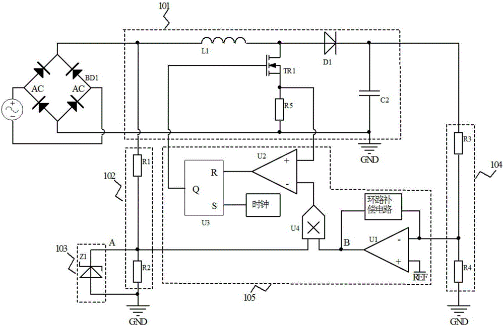
[0040] The first embodiment of the present invention is as figure 2 shown. A switching power supply, comprising an AC-DC power supply circuit and a PFC control circuit, wherein the AC-DC power supply circuit comprises a BD1 rectifier circuit and a voltage conversion circuit 101, the voltage conversion circuit 101 is also a main power circuit, and the PFC control circuit is located between the rectification circuit and the voltage conversion circuit 101. Between the voltage conversion circuits; the PFC control circuit includes an input detection circuit 102, a waveform shaping circuit 103, an output detection circuit 104, and a feedback control circuit 105. The input detection circuit 102 detects the rectified bus voltage and provides a reference voltage for the feedback control circuit Waveform; Output detection circuit 104 detects the voltage output by the voltage conversion circuit, and provides an output sampling voltage for the feedback control circuit; The feedback contr...
no. 2 example
[0061] In Embodiment 1, input in a wide range, such as the common input voltage range of 85V to 265V, figure 2 The shape of the voltage waveform at point A will change. In the first embodiment, only one zener diode is used to chop the input sampling voltage. If the input voltage changes, the relative position of the cut is different, and the obtained waveform shape of point A is also different. When the input voltage is 85V and 265V respectively, figure 2 The voltage waveform at point A is as follows Figure 7 shown. When the input voltage is high, the relative position of the cut wave is lower, and the difference with the original sine wave is greater, the PF value will be lower, but the output ripple will be smaller.
[0062] In order to make the working state change insignificantly when inputting high and low voltage. presents a second embodiment of the circuit as Figure 8 shown. Compared with Embodiment 1, the waveform shaping circuit 103 is different in that a co...
PUM
 Abstract
Description
Claims
Application Information
 - R&D
- Intellectual Property
- Life Sciences
- Materials
- Tech Scout
- Unparalleled Data Quality
- Higher Quality Content
- 60% Fewer Hallucinations
Browse by: Latest US Patents, China's latest patents, Technical Efficacy Thesaurus, Application Domain, Technology Topic, Popular Technical Reports.
© 2025 PatSnap. All rights reserved.Legal|Privacy policy|Modern Slavery Act Transparency Statement|Sitemap|About US| Contact US: help@patsnap.com


