
Power supply circuit and control method therefor

一种电源电路、电源电压的技术,应用在电池电路装置、电路装置、控制/调节系统等方向,能够解决功率损失大、电压范围窄、开关工作自身不能进行等问题

Active Publication Date: 2016-12-07
LAPIS SEMICON CO LTD
View PDF8 Cites 1 Cited by
  • Summary
  • Abstract
  • Description
  • Claims
  • Application Information

AI Technical Summary

Problems solved by technology

[0003] It is preferable to operate with a wide range of power supply voltages in communication equipment that operates from a battery or the like as a power source, but the switching regulator converts the power supply voltage supplied from the power supply to an inductor / capacitor as necessary to output Therefore, although there is an advantage of less power loss, when the power supply voltage decreases, the conversion efficiency decreases or the switching operation itself becomes impossible, etc., and the preferred voltage range input from the power supply voltage is narrow.
[0004] On the other hand, the series regulator can handle a wide voltage range and finely control the output transistor, so it can obtain an optimal output voltage. However, when the power supply voltage is high, it is necessary to lower the voltage to the output The power is converted into heat, and the power loss is large

Method used


Image

  • Power supply circuit and control method therefor
  • Power supply circuit and control method therefor
  • Power supply circuit and control method therefor

Examples


no. 1 approach

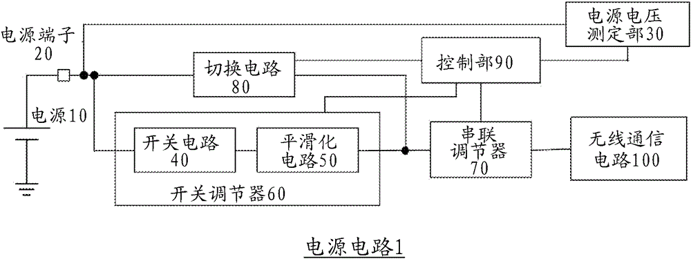
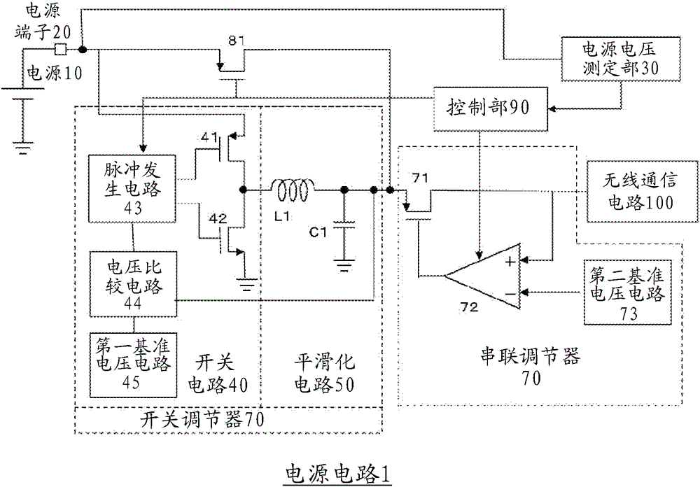
[0029] figure 1 It is a block diagram of the power supply circuit of the present invention. The power supply circuit 1 has: a power supply 10 for supplying a power supply voltage, a power supply terminal 20 to which the power supply 10 is input, a power supply voltage measuring unit 30 connected to the power supply terminal 20, a switch circuit 40 connected to the power supply terminal 20, and a power supply terminal 20 connected to the switch circuit 40. The switching regulator 60 of the smoothing circuit 50, the series regulator 70 connected to the switching regulator 60, the switching circuit 80 connected to the power supply terminal 20 at one end and connected between the switching regulator 60 and the series regulator 70 at the other end, The switching regulator 60 , the series regulator 70 , and the control unit 90 controlled by the switching circuit 80 , and the wireless communication circuit 100 to which the output voltage from the series regulator 70 is supplied.

[...


PUM


Abstract

A power source circuit includes a power source terminal for inputting a power source voltage; a switching regulator including a switching circuit connected to the power source terminal and a smoothing circuit connected to the switching circuit; a series regulator connected to the switching regulator in series; a switching portion; and a control portion. The smoothing circuit includes a capacitor and an inductor to output a first voltage. The series regulator is connected to the switching circuit and the smoothing circuit in series to output a second voltage. The switching portion supplies the power source voltage to the series regulator. The control portion outputs a switching signal for controlling the switching portion to turn on or off according to the power source voltage.

Description

technical field [0001] The present invention relates to a power supply circuit and a control method thereof, and particularly relates to a power supply circuit and a control method thereof for use in wireless communication LSIs and the like. Background technique [0002] Conventionally, in LSIs (integrated circuits) used for wireless communications, etc., a power supply circuit is provided to remove fluctuations and noise in supplied voltage, and to supply an output voltage with a constant voltage and less noise to internal circuits. Furthermore, as a power supply circuit for supplying such an output voltage, a step-down switching regulator (switching regulator) composed of a switching element and an inductor / capacitor, and a series circuit composed of an operational amplifier and a linearly operating output transistor are known. Regulator (series regulator). [0003] It is preferable to operate with a wide range of power supply voltages in communication equipment that oper...

Claims


Application Information

Patent Timeline
Patent Type & Authority Applications(China)
IPC IPC(8): H02M3/155H02M1/36H02M1/00
CPCG05F1/563G05F5/00H02M3/158H02M3/1588H02M1/0032H02M1/0045H02M1/0048Y02B70/10H02M3/1584H02J2207/20
Inventor 太矢隆士
Owner LAPIS SEMICON CO LTD
Features
  • Generate Ideas
  • Intellectual Property
  • Life Sciences
  • Materials
  • Tech Scout
  • Unparalleled Data Quality
  • Higher Quality Content
  • 60% Fewer Hallucinations
Learn More