
Semi-automatic chamfering machine

A chamfering machine, semi-automatic technology, applied in the direction of grinding automatic control device, grinding frame, grinding drive device, etc., can solve the problems of unsatisfactory delivery, low chamfering efficiency, and extended delivery time. Achieve the effect of reducing the work intensity of employees and improving chamfering efficiency

Inactive Publication Date: 2016-12-14
湖南晶讯光电股份有限公司
View PDF5 Cites 4 Cited by
  • Summary
  • Abstract
  • Description
  • Claims
  • Application Information

AI Technical Summary

Problems solved by technology

[0002] At present, chamfering machines in the LCD industry use manual chamfering machines to chamfer LCDs. Due to low chamfering efficiency, insufficient control accuracy, and high defects in external scratches and damage, many LCD manufacturers produce chamfered products. Processing by other manufacturers
This increases the manufacturing cost and prolongs the delivery time, which cannot meet the needs of fast delivery of electronic products.

Method used


Image

  • Semi-automatic chamfering machine
  • Semi-automatic chamfering machine
  • Semi-automatic chamfering machine

Examples


Embodiment Construction

[0018] In order to make the technical means, creative features, goals and effects achieved by the present invention easy to understand, the present invention will be further described below in conjunction with specific embodiments.

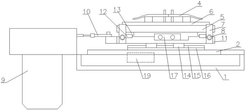
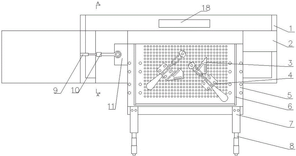
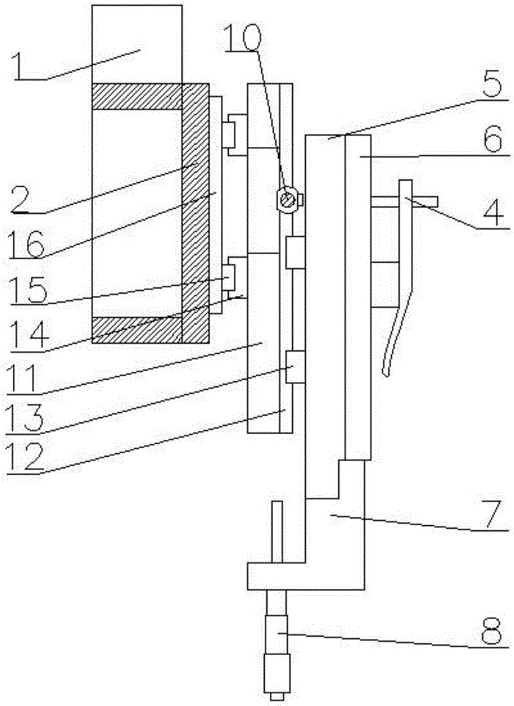
[0019] see figure 1 with image 3 , the present invention provides a technical solution: a semi-automatic chamfering machine, including a base frame 1, a bottom plate 2, a positioning plate 3, a forceps 4, a workbench 5, a micrometer 6, a motor 9, a movable slide plate 11 and a cylinder 17, a base The top of frame 1 is provided with base plate 2, and the top of base plate 2 is provided with slide rail fixed plate 16, and the top of slide rail fixed plate 16 is provided with slide rail 2 15, and slide rail 2 15 is provided with slide block 2 14, movable slide plate 11 Connect slide rail two 15 by slide block two 14, the top of movable slide plate 11 is provided with slide rail one 12, the top of slide rail one 12 is placed with slide block one 13,...


PUM


Abstract

The invention provides a semi-automatic chamfering machine. The semi-automatic chamfering machine comprises a base frame, a bottom plate, locating plates, locking pliers, a work table, micrometers, a motor, a movable sliding plate and an air cylinder, wherein the bottom plate is arranged on the base frame; a sliding rail fixing plate is installed on the bottom plate, a second sliding rail is arranged on the sliding rail fixing plate, a plurality of second sliding blocks are arranged on the second sliding rail, the movable sliding plate is connected to the second sliding rail through the second sliding blocks, a first sliding rail is arranged on the movable sliding plate, a plurality of first sliding blocks are arranged on the first sliding rail, and the air cylinder is arranged on one side of the first sliding rail; the motor is arranged on the left side of the base frame and is connected to the movable sliding plate through a pull rod; the work table is arranged on the first sliding blocks, the front side of the work table is connected to a micrometer fixing frame, and the micrometer fixing frame is provided with the micrometers; and a PLC is arranged inside the base frame. Compared with the prior art, the semi-automatic chamfering machine has the beneficial effects that propulsive assistance of the air cylinder replaces manual thrust, and the micrometers limit a jig so that accuracy control can be realized.

Description

technical field [0001] The invention is a semi-automatic chamfering machine, which belongs to the field of LCD chamfering equipment. Background technique [0002] At present, chamfering machines in the LCD industry use manual chamfering machines to chamfer LCDs. Due to low chamfering efficiency, insufficient control accuracy, and high defects in external scratches and damage, many LCD manufacturers produce chamfered products. Other manufacturers do the processing on their behalf. This increases the manufacturing cost and prolongs the delivery time, which cannot meet the current demand for fast delivery of electronic products. Contents of the invention [0003] Aiming at the deficiencies in the prior art, the object of the present invention is to provide a semi-automatic chamfering machine to solve the problems raised in the above-mentioned background technology. The present invention is easy to use, easy to operate, ingenious in design, and improves the market competitive...

Claims


Application Information

Patent Timeline
Patent Type & Authority Applications(China)
IPC IPC(8): B24B9/10B24B41/00B24B41/02B24B47/08B24B51/00
CPCB24B9/10B24B41/005B24B41/02B24B47/08B24B51/00
Inventor 贺术春
Owner 湖南晶讯光电股份有限公司
Learn More