Polishing device for construction steel bar

A technology for building steel bars and bracket devices, which is applied to grinding/polishing safety devices, grinding machines, grinding racks, etc. High grinding efficiency and simple structure

Active Publication Date: 2016-12-14
广西华业建筑工程有限公司
View PDF7 Cites 21 Cited by
  • Summary
  • Abstract
  • Description
  • Claims
  • Application Information

AI Technical Summary

Problems solved by technology

[0003] During the operation of this kind of steel bar grinding, the flying chips generated due to the rapid operation of the grinding wheel are likely to be dangerous to the operator
However, some current security shielding measures are often run manually
This method is likely to cause safety hazards when the operator forgets to operate the safety shield to drop, and setting a special power drive mechanism to detect and execute the fall of the safety shield will increase the cost and inconvenience maintenance

Method used


Image

  • Polishing device for construction steel bar

Examples


Embodiment Construction

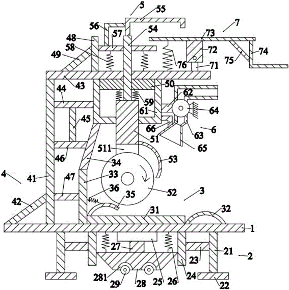
[0020] Such as figure 1 As shown, the present invention is used for building steel bar grinding device and comprises bottom plate 1, the roller device 2 that is positioned at the bottom of described bottom plate 1, the magnet device 3 that is positioned at the top of described bottom plate 1, the support device 4 that is positioned at the left side of described magnet device 3, The grinding structure 5 arranged on the support device 4 , the air blowing device 6 located on the right side of the grinding structure 5 and the adjusting device 7 located above the support device 4 .

[0021] Such as figure 1 As shown, the base plate 1 is in the shape of a cuboid, and the base plate 1 is placed horizontally.

[0022] Such as figure 1 As shown, the roller device 2 includes a first support bar 21 located on the left and right sides below the bottom plate 1, a first pad 22 located below the first support bar 21, and a first pad 22 arranged on the first support bar. 21, the first positi...


PUM


Abstract

The invention discloses a polishing device for a construction steel bar, comprising a bottom plate, a roller device, a magnet device, a support device, a polishing structure, a blowing device and a regulating device; the roller device comprises a first supporting rod, a first cushion block, a first cross rod, a first locating rod, an air cylinder, a first spring, a pushing rod, a supporting block and a first roller; the magnet device comprises a first magnet, a bent rod, a second magnet, a third magnet, a clamping rod and a second spring; the support device comprises a second supporting rod, a first inclined rod, a second cross rod, a third cross rod, a first vertical rod, a fourth cross rod, a fifth cross rod, a second vertical rod and a second inclined rod; the polishing structure comprises a moving rod, a polishing wheel, a baffle, a third vertical rod, a locating rack, a first support, a sixth cross rod, a third spring, a locating block and a fourth spring; and the blowing device comprises a fixed frame, a first connecting rod, a draught fan, a blow pipe and a blow hopper. The polishing device can be used for rapidly polishing the steel bar and is high in polishing efficiency.

Description

technical field [0001] The invention relates to the technical field of construction machinery, in particular to a device for grinding steel bars in construction. Background technique [0002] In the field of construction, it is often necessary to grind the steel bars, such as grinding off the ribs or rust on the head, so as to add strain gauges or facilitate knotting of steel bars. [0003] During the operation process of such steel bar grinding, flying chips generated due to the fast running of the grinding wheel are likely to cause danger to the operator. However, some current security shielding measures are often run manually. This method is likely to cause potential safety hazards when the operator forgets to operate the safety shield to drop, and setting a special power drive mechanism to detect and execute the fall of the safety shield will cause an increase in cost and inconvenience in maintenance. [0004] Therefore, it is necessary to provide a new technical solut...

Claims


Application Information

Patent Timeline
Patent Type & Authority Applications(China)
IPC IPC(8): B24B27/033B24B55/06B24B41/02B24B41/06B03C1/02
CPCB03C1/02B24B27/033B24B41/02B24B41/06B24B55/06
Inventor 李建南
Owner 广西华业建筑工程有限公司
Why Eureka
Try Eureka