Two-way adjusting mechanism

A two-way adjustment, X-axis technology, applied in the direction of conveyor objects, transportation and packaging, etc., can solve the problem of inability to perform two-dimensional positioning, and achieve the effect of simple structure and convenient use

Inactive Publication Date: 2016-12-14
SUZHOU SANFU AUTOMATION TECH CO LTD
0 Cites 0 Cited by

AI-Extracted Technical Summary

Problems solved by technology

[0005] In automatic production and processing, the transportation of ornaments is mostly carried out by hand, and the transportation of a little farther is conveyed by a trolley through a tray, or conveyed by a conveyor belt, but the conveyor belt can only be conveyed in a straight line, and cannot carry out two-dimensional ...

Method used

During actual use, moving block 8 moves on guide rod 6, forms two-dimensional plane by X-axis motor 3, Y-axis motor 4, makes m...

Abstract

The invention relates to a two-way adjusting mechanism. The two-way adjusting mechanism comprises a frame body, a base, an X-axis motor, a Y-axis motor, rolling wheels, guide rods, toothed belt buckles and movable blocks and is characterized in that the guide rods are two sets, and each set of guide rods are two parallel guide rods; the X-axis motor is arranged on one side of the frame body; the two guide rods perpendicular to the X-axis motor are arranged on the frame body; the two guide rods parallel to the X-axis motor are arranged on the two guide rods perpendicular to the X-axis motor through the movable blocks; one movable block is slidably arranged on the two guide rods parallel to the X-axis motor; each movable block is provided with one toothed belt buckle; the output ends of the X-axis motor and the Y-axis motor are each provided with one rolling wheel; the rolling wheels at the output ends of the X-axis motor and the Y-axis motor and the rolling wheels on the other sides of the corresponding guide rods penetrate through the toothed belt buckles through transmission belts to form a closed loop; and the base is arranged under the frame body. During actual usage, the movable blocks move on the guide rods, a two-dimensional plane is formed by the X-axis motor and the Y-axis motor so that the movable blocks can move freely within the prescribed range, and thus the requirement of two-dimensional locating is met.

Application Domain

Conveyor parts

Technology Topic

Through transmissionEngineering +3

Image

  • Two-way adjusting mechanism

Examples

  • Experimental program(1)

Example Embodiment

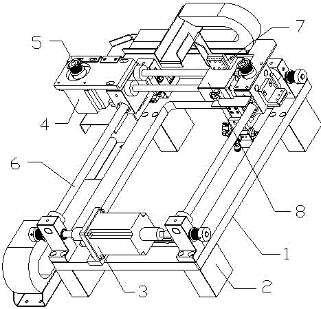
[0013] The present invention will be further described below in conjunction with the drawings.
[0014] The two-way adjustment mechanism includes a frame body 1, a base 2, an X-axis motor 3, a Y-axis motor 4, a roller 5, a guide rod 6, a toothed belt buckle 7, and a moving block 8. It is characterized in that the guide rods 6 are two groups, each Group guide rods 6 are two parallel, X-axis motor 3 is set on one side of frame 1, two guide rods 6 perpendicular to X-axis motor 3 are set on frame 1, two parallel to X-axis motor 3 The guide rod 6 is arranged on two guide rods 6 perpendicular to the X-axis motor 3 through a moving block 8. A moving block 8 is slidably arranged above the two guide rods 6 parallel to the X-axis motor 3, which is connected to the X-axis motor 3. Two vertical guide rods 6 are respectively provided with moving blocks 8 slidably, each moving block 8 is provided with a toothed belt buckle 7, and the two guide rods 6 parallel to the X-axis motor 3 are provided with a Y-axis motor outside 4. The output ends of the Y-axis motor 4 and X-axis motor 3 are both provided with a roller 5. The roller 5 and the roller 5 on the other side of the corresponding guide rod 6 pass through the toothed belt buckle 7 through the transmission belt to form a closed loop. A base 2 is provided under the body 1. The toothed belt buckle 7 is L-shaped. X-axis motor 3 is a bidirectional output motor. The output end of the Y-axis motor 4 faces upward. The frame body 1 is in the shape of a box, and the middle part corresponds to the movable position of the movable block 8 above the two guide rods 6 parallel to the X-axis motor 3 is hollowed out.
[0015] In actual use, the moving block 8 moves on the guide rod 6, and a two-dimensional plane is formed by the X-axis motor 3 and the Y-axis motor 4, so that the moving block 8 can move freely within a specified range, thereby meeting the needs of two-dimensional positioning.
[0016] The foregoing only illustrates the technical concept and characteristics of the invention, and its purpose is to enable those of ordinary skill in the art to understand the content of the invention and implement it accordingly, and does not limit the protection scope of the invention. All equivalent changes or modifications made according to the essence of the present invention should be covered by the protection scope of the present invention.

PUM

no PUM

Description & Claims & Application Information

We can also present the details of the Description, Claims and Application information to help users get a comprehensive understanding of the technical details of the patent, such as background art, summary of invention, brief description of drawings, description of embodiments, and other original content. On the other hand, users can also determine the specific scope of protection of the technology through the list of claims; as well as understand the changes in the life cycle of the technology with the presentation of the patent timeline. Login to view more.

Similar technology patents

Air bag module

InactiveUS20070057487A1simple structureeasily manufacture
Owner:HYUNDAI MOBIS CO LTD

Biometric identification apparatus

InactiveUS20080037001A1perform accurately and rapidlysimple structure
Owner:HITACHI MEDIA ELECTORONICS CO LTD

Body condition measuring device

InactiveUS20050234351A1simple structure
Owner:DENSO CORP

Classification and recommendation of technical efficacy words

  • Simple structure
  • easy to use

Sharing system for air-conditioning coat

InactiveCN107440179ASimple structureeasy to wear
Owner:QINGDAO HAIER AIR CONDITIONER GENERAL CORP LTD

Feeding device of sorter of batteries plate

InactiveCN101357717ASimple structurecooperate well
Owner:NANJING NORMAL UNIVERSITY

Emergency parachuting device and method for multiple-rotor unmanned aerial vehicle

InactiveCN103895870Aavoid aircraft crashSimple structure
Owner:SOUTH CHINA AGRI UNIV +1

Quick pipe connector

Owner:YANG RICHARD

Laser assisted total joint arthroplasty

InactiveUS20090234360A1easy to use
Owner:ALEXANDER VLADIMIR

Enclosure for a portable hemodialysis system

ActiveUS20090114582A1easy to use
Owner:DEKA PROD LLP
Why Eureka
Try Eureka