Quantum optical fiber interferometer

An optical fiber interferometer and interferometer technology, applied in the field of precision measurement, can solve the problems of limited classical shot noise limit and other problems, and achieve the effect of high integration and small size

Active Publication Date: 2016-12-14
NANJING UNIV
View PDF6 Cites 12 Cited by
  • Summary
  • Abstract
  • Description
  • Claims
  • Application Information

AI Technical Summary

Problems solved by technology

[0004] Purpose of the invention: The present invention aims at the problems existing in the prior art, and provides a quantum optical fiber interferometer to overcome the defect of the existing interferometer system limited by the classical shot noise limit. phase measurement

Method used


Image

  • Quantum optical fiber interferometer
  • Quantum optical fiber interferometer
  • Quantum optical fiber interferometer

Examples


Embodiment Construction

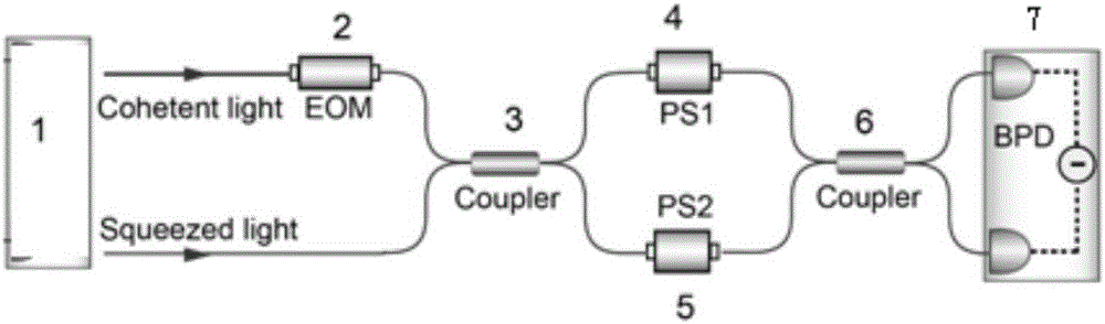
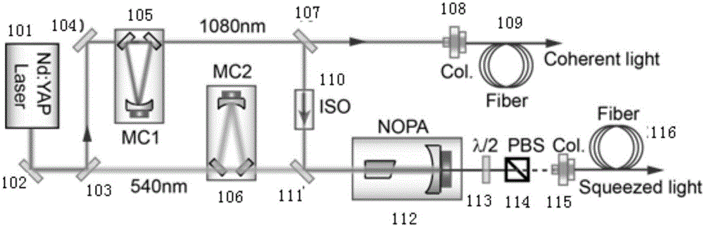
[0029] like figure 1 As shown, the quantum optical fiber interferometer of this embodiment includes a quantum squeeze light source 1, an electro-optic modulator 2, a first optical fiber beam splitter 3, a first optical fiber phase shifter 4, a second optical fiber phase shifter 5, a second optical fiber Beam splitter 6 and balanced detector 7. Wherein, the quantum squeezed light source 1 is specifically a continuous variable squeezed light source for emitting coherent light and quantum squeezed light. The electro-optic modulator 2 is connected to the quantum squeeze light source 1, and is used to receive the coherent light emitted by the quantum squeeze light source and perform high-frequency amplitude modulation. The electro-optic modulator 2 is specifically a waveguide-type electro-optic amplitude modulator with a half-wave voltage of 3.5V. The modulation frequency is 2.5MHz. The first optical fiber beam splitter 3 is connected to the quantum squeeze light source 1 and the...


PUM


Abstract

The invention discloses a quantum optical fiber interferometer comprising a quantum compression light source, an electro-optic modulator, a first optical fiber splitter, a first optical fiber phase shifter, a second optical fiber phase shifter, a second optical fiber splitter and a balance detector. The defects that the existing interferometer system is limited by the classic shot noise limit can be overcome, and the system can perform low frequency phase measurement by using a high frequency compression source.

Description

technical field [0001] The invention relates to the technical field of precision measurement, in particular to a quantum optical fiber interferometer. Background technique [0002] In the field of precision measurement, the measurement of many physical quantities is attributed to the measurement of the phase, so the interferometer has become the most common experimental device in precision measurement, in basic scientific research (such as the measurement of basic physical constants) and practical engineering applications (such as navigation positioning, resource exploration) all play a vital role. At present, the long baseline laser interferometer used for gravitational wave detection has a sensitivity of ~10 -23 εHz -1 / 2 , is currently the most sensitive interferometer. However, this kind of free-space interferometer is complex in structure and bulky, and is easily affected by ambient temperature, sound and vibration, making interferometric measurement unstable and diff...

Claims


Application Information

Patent Timeline
Patent Type & Authority Applications(China)
IPC IPC(8): G01B9/02
CPCG01B9/02062
Inventor 刘芳张勇肖士雄郭佳乐魏丹肖敏
Owner NANJING UNIV
Why Eureka
Try Eureka