Method for large-area representation of graphite/silicon/amorphous carbon composite structure silicon-carbon cathode powder body

An amorphous carbon and composite structure technology, applied to structural parts, battery electrodes, electrical components, etc., can solve the problems of single characterization, inability to simultaneously characterize the distribution and structure of silicon-carbon anode components in a large area, and time-consuming problems, to achieve Simple operation effect

Inactive Publication Date: 2016-12-14
HEFEI GUOXUAN HIGH TECH POWER ENERGY
View PDF3 Cites 13 Cited by
  • Summary
  • Abstract
  • Description
  • Claims
  • Application Information

AI Technical Summary

Problems solved by technology

However, these methods generally have the problem of single characterization and the inability to simultaneously characterize the powder components and structure in a large area.
For example, XRD can analyze the silicon-carbon composition in the negative electrode powder, but it cannot give the distribution of the silicon-carbon composition; scanning electron microscopy can analyze the surface morphology of the powder particles, but it cannot give a large area of ​​the silicon-carbon composition. Partition distribution and its structural information; transmission electron microscopy can characterize the internal structure and component distribution of small particles, but it cannot simultaneously characterize the component distribution and structural consistency of silicon-carbon anodes in a large area; elemental imaging based on X-ray spectroscopy (EDX) Analytical methods can give the elemental distribution of silicon-carbon anodes, but it is time-consuming to use this method to characterize large-area silicon-carbon anode materials
In addition, both amorphous carbon and graphite are carbon-based materials, and the elemental analysis imaging method cannot distinguish the distribution of the two materials

Method used


Image

  • Method for large-area representation of graphite/silicon/amorphous carbon composite structure silicon-carbon cathode powder body
  • Method for large-area representation of graphite/silicon/amorphous carbon composite structure silicon-carbon cathode powder body
  • Method for large-area representation of graphite/silicon/amorphous carbon composite structure silicon-carbon cathode powder body

Examples


Embodiment 1

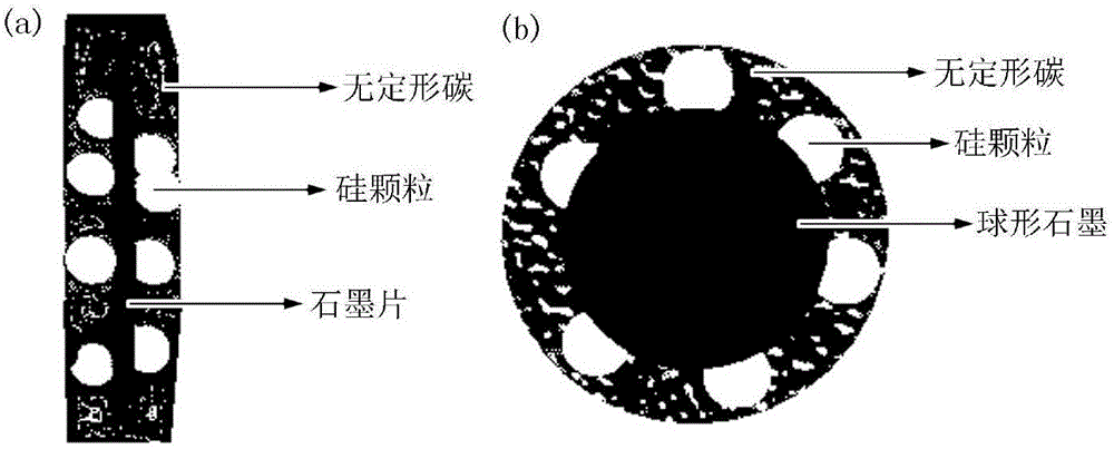
[0034]The graphite-silicon-amorphous carbon composite structure silicon-carbon negative electrode powder selected in this embodiment is formed by attaching silicon particles to the surface of spherical graphite and then coating a layer of amorphous carbon. Its structure is as follows figure 1 (b) shown.

[0035] (1) Pretreatment of silicon-carbon composite structure powder: Weigh 0.03g of graphite / silicon particles / amorphous carbon composite structure silicon-carbon anode powder, place it between two glass sheets with clean and flat surfaces and press firmly Compact it on the powder so that it does not fall off and the surface of the powder is smooth. The area of ​​the powder after compaction is about 3.14 to 7.065 square centimeters.

[0036] (2) Acquisition of single Raman spectrum: Place the silicon-carbon anode powder material with a flat surface in step (1) on the sample test bench of the laser Raman instrument (HORRIBA, LabRAM HR Evol), select the test conditions to ensu...

Embodiment 2

[0044] The graphite-silicon-amorphous carbon composite structure silicon-carbon negative electrode powder formed by the silicon particles attached to the spherical graphite sheet and then coated with a layer of amorphous carbon in this embodiment has a structure such as figure 1 (a) shown.

[0045] (1) Pretreatment of silicon-carbon composite structure powder: First, weigh 0.06g of graphite sheet / silicon particle / amorphous carbon composite structure silicon-carbon negative electrode powder, and place it between two glass sheets with clean and flat surfaces And forcefully press it on the powder to compact it so that it does not fall off and the surface of the powder is smooth. The area of ​​the powder after compaction is about 3.14 to 7.065 square centimeters.

[0046] (2) Acquisition of single Raman spectrum: Place the silicon-carbon anode powder material with a flat surface in step (1) on the sample test bench of the laser Raman instrument (HORRIBA, LabRAM HR Evol), select th...

Embodiment 3

[0051] According to the mass ratio of spherical graphite: silicon particle powder: amorphous carbon = 7:2:1, weigh a certain amount of spherical graphite, silicon particle powder, and amorphous carbon respectively and place them in a mortar, and mix them manually and mechanically for 5~ 10 minutes, then add ethanol and mix mechanically for 5-10 minutes, dry in an oven after mixing, take it out and then perform mechanical mixing for 5-10 minutes to ensure mixing uniformity, and obtain graphite-silicon-amorphous carbon mixed samples .

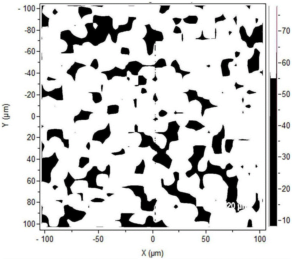
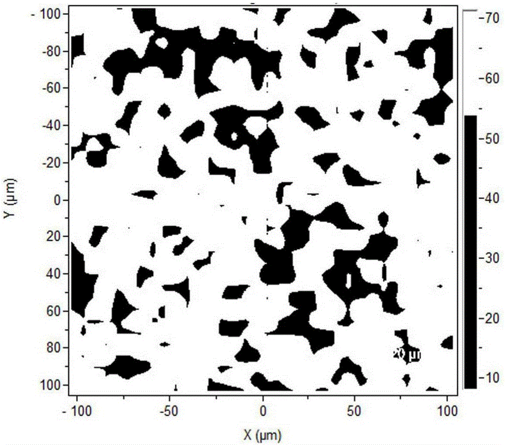
[0052] The graphite-silicon-amorphous carbon mixed sample prepared above is characterized by the treatment method of Example 1, the ratio of silicon peak, carbon D peak, carbon G peak, carbon D peak / carbon G peak, carbon G peak / carbon D The peak ratios of these five Raman imaging images are as Figure 6 , 7 As shown, the comparison can draw conclusions: first, the intensity distribution of Si peak, carbon D peak, and carbon G peak is very uneve...


PUM


Abstract

The invention discloses a method for large-area representation of a graphite / silicon / amorphous carbon composite structure silicon-carbon cathode powder body. The method comprises the following steps: placing the graphite / silicon / amorphous carbon composite structure silicon-carbon cathode powder body in the middle of a glass sheet with two flat surfaces, and compacting and flattening the powder body; testing the powder body with a laser Raman spectrometer, adjusting the peak of an obtained common Raman single spectrum to appear at positions near to 520 cm<-1>, 1,350 cm<-1> and 1,590 cm<-1>, and obtaining a test condition; obtaining a Raman imaging spectrum according to the test condition; respectively forming Raman imaged pictures for the intensities of a silicon peak, a carbon D peak and a carbon G peak, respectively imaging a ratio of the carbon D peak to the carbon G peak and a ratio of the carbon G peak to the carbon D peak, and judging whether the components and the structures in the powder body are consistent. The representation method disclosed by the invention is simple and quick, and can realize large-area representation of the distribution of silicon-carbon cathode components and research the structure consistency, so that the method has extremely high application prospect.

Description

technical field [0001] The invention relates to a method for characterizing negative electrode powders of lithium ion batteries, in particular to a method for characterizing graphite / silicon / amorphous carbon composite structure silicon-carbon negative electrode powders in a large area. Background technique [0002] Due to its high theoretical lithium storage capacity (4200mAh / g), silicon-based anode materials have aroused the research enthusiasm of many scientists. However, due to the huge volume change of the silicon-based material during the charge and discharge process, the electrode material of the battery will be cracked, pulverized, and structurally collapsed during the cycle. Therefore, the silicon material is mainly compounded with graphite (graphite sheet, spherical graphite, etc.), and then coated with a layer of amorphous carbon to prepare a silicon carbon material with a composite structure of graphite / silicon / amorphous carbon, which is used as the negative ele...

Claims


Application Information

Patent Timeline
Patent Type & Authority Applications(China)
IPC IPC(8): H01M4/36
CPCH01M4/364Y02E60/10
Inventor 李中波夏劲
Owner HEFEI GUOXUAN HIGH TECH POWER ENERGY
Why Eureka
Try Eureka