
Raman super-resolution microimaging system based on structured light illumination and imaging method

A technology of structured light illumination and microscopic imaging, which is applied in Raman scattering, material analysis by optical means, and material analysis, etc., can solve the problems of inability to quickly image the whole surface of the sample, photodamage of the sample by fluorescence bleaching, and poor stability, etc. Achieve high-speed super-resolution Raman imaging, high sensitivity, and low requirements

Active Publication Date: 2018-06-01
CHANGCHUN INST OF APPLIED CHEMISTRY - CHINESE ACAD OF SCI
View PDF3 Cites 6 Cited by
  • Summary
  • Abstract
  • Description
  • Claims
  • Application Information

AI Technical Summary

Problems solved by technology

[0005] The purpose of the present invention is to solve the problem that the structured light super-resolution fluorescence microscopy technology in the prior art relies on fluorescent labels, has poor specificity, and is prone to fluorescent bleaching and photodamage when observing samples for a long time, while the Raman super-resolution microscopy imaging technology is based on The method of near-field scanning has poor stability, and the technical problem that it is impossible to perform comprehensive and rapid imaging of the sample provides a Raman super-resolution microscopic imaging system and imaging method based on structured light illumination.

Method used


Image

  • Raman super-resolution microimaging system based on structured light illumination and imaging method
  • Raman super-resolution microimaging system based on structured light illumination and imaging method
  • Raman super-resolution microimaging system based on structured light illumination and imaging method

Examples


Embodiment Construction

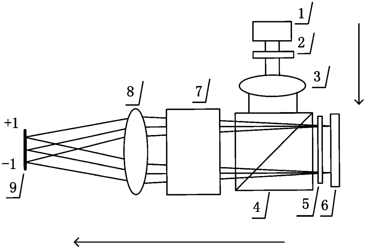
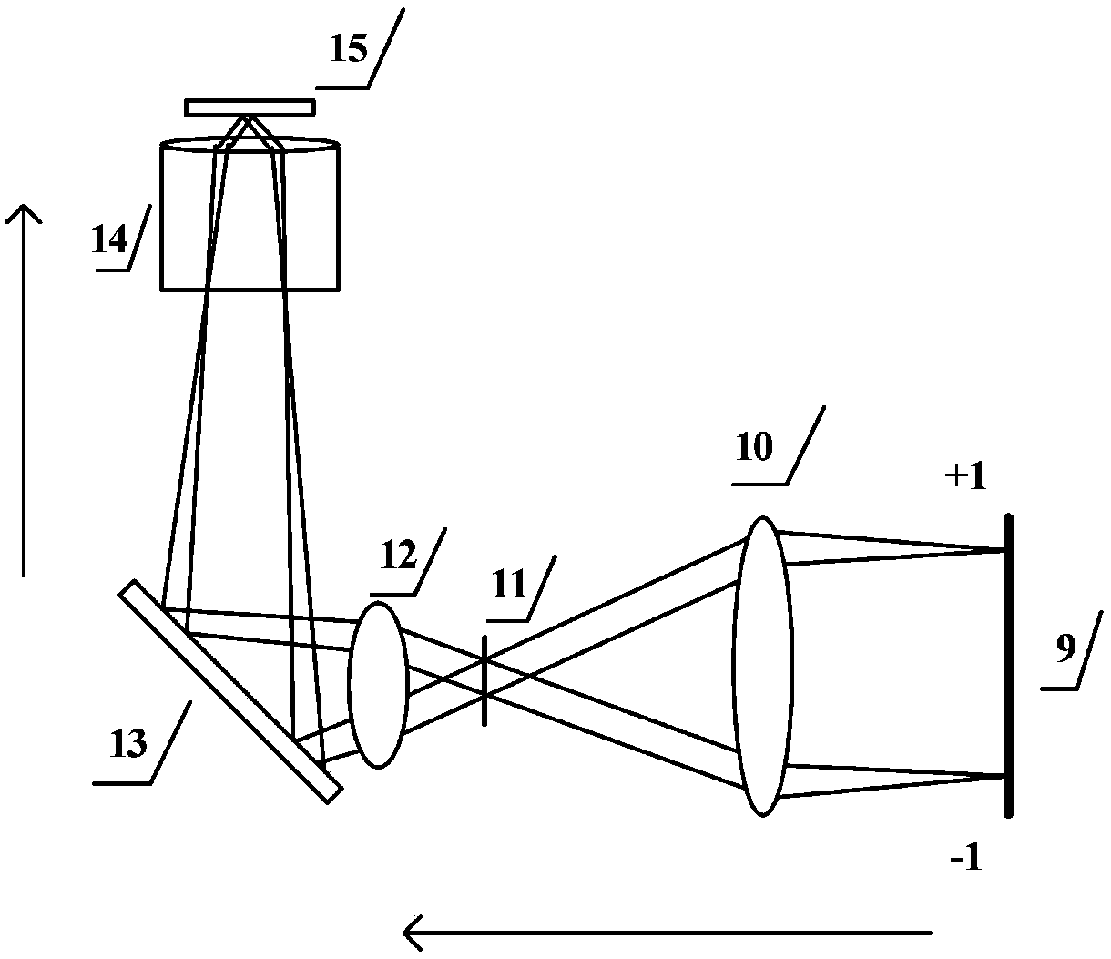
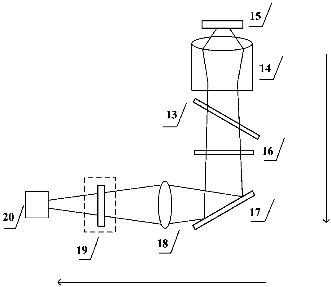
[0035] Attached below Figure 1-6 The present invention is described in further detail.

[0036] Such as Figure 5 As shown, the Raman super-resolution microscopy imaging system based on structured light illumination includes a structured light generation device, a Raman signal excitation device and a disposable Raman imaging device.

[0037] Among them, such as figure 1 As shown, the structured light generating device includes a laser 1, an excitation filter 2, a beam expander group 3, a PBS beam splitter 4, a half-wave plate 5, a ferroelectric liquid crystal 6, a polarization modulation component 7, and a first focusing lens 8 and mask board9. The laser 1 emits monochromatic excitation light, which is filtered by the excitation filter 2 in turn. After the beam expander group 3 expands the beam, it enters the PBS beam splitter 4 for beam splitting. The polarized light in the S direction passes through the half-wave plate 5 and reaches the ferroelectric liquid crystal. 6. ...


PUM

PropertyMeasurementUnit
Wavelengthaaaaaaaaaa
Particle sizeaaaaaaaaaa

Abstract

The invention discloses a Raman super-resolution microimaging system based on structured light illumination and an imaging method and solves the technical problems in the prior art that the structuredlight super-resolution fluorescence microscopy relies on a fluorescent marker and thus has poor specificity, fluorescence bleaching and light injury often happen after long-time observation of the sample, and the Raman super-resolution microimaging technology is implemented based on a near field scanning way and thus has relatively low stability and cannot perform panoramic fast imaging of the sample. The imaging system disclosed by the invention comprises a structured light generation device, a Raman signal excitation device and a one-time Raman imaging device. Through combination of the structured light super-resolution fluorescence microscopy and the Raman super-resolution microimaging technology, the imaging system realizes non-marked, panoramic and fast super-resolution imaging, andcan be applied to the research directions such as cell membranes, artificial phospholipid membranes, artificial nano pores, endocytosis / transfer single molecule and particle system, mechanism of virusentering cells, dynamic process of molecules in living cell, interaction of nano cells and biological effect.

Description

technical field [0001] The invention belongs to the technical field of super-resolution imaging of microscopic particles, and in particular relates to a Raman super-resolution microscopic imaging system and imaging method based on structured light illumination. Background technique [0002] In the field of life sciences, super-resolution imaging around living cells has always been a hot spot in instrument development. In recent years, several far-field fluorescence super-resolution microscopes have emerged, breaking through the optical diffraction limit and successfully achieving super-resolution imaging of biological samples. Among them, structured light super-resolution fluorescence microscopy (SIM) has lower requirements for sample labeling and faster imaging speed, and can realize super-resolution imaging of living cells. However, because it still relies on fluorescent labeling, its specificity is poor, and it is prone to fluorescent bleaching and photodamage when obser...

Claims


Application Information

Patent Timeline
IPC IPC(8): G01N21/65
CPCG01N21/658
Inventor 王宏达孙佳音初宏亮
Owner CHANGCHUN INST OF APPLIED CHEMISTRY - CHINESE ACAD OF SCI
Learn More