
Heat-preservation paint barrel for casting

A technology for thermal insulation paint and paint bucket, applied in the field of casting equipment, can solve the problems of unevenness, low work efficiency and high cost, and achieve the effects of improving thermal insulation performance, saving time and labor, and high thermal insulation performance

Inactive Publication Date: 2016-12-21
娄土岭
View PDF4 Cites 4 Cited by
  • Summary
  • Abstract
  • Description
  • Claims
  • Application Information

AI Technical Summary

Problems solved by technology

[0002] The paint produced by the paint production line can be divided into cold paint and hot paint. Both cold paint and hot paint need to maintain a certain temperature for the supply of materials in the next process. The paint and hot paint are used for heat preservation separately. The traditional paint insulation barrel includes a barrel body and a lid covering the mouth of the barrel. The barrel body includes an inner wall and an outer wall covering the inner wall. There is a vacuum between the inner wall and the outer wall, and the vacuum layer ensures that the paint The temperature of the heat preservation barrel, the heat preservation effect of the paint heat preservation barrel with this structure is not ideal, which is not conducive to the long-term effective heat preservation of the paint
[0003] In addition, the method used in the lost foam casting process to coat the casting model is the dip coating method. The coating must be stirred reasonably before the dip coating of the lost foam pattern. It is best to keep stirring slowly during the dip coating process to prevent the coating from Air is involved in the medium, which will affect the coating effect
In the process of use, the paint often precipitates, is uneven, or even hardens due to too long a period of time. This requires frequent stirring of the paint in the bucket to ensure the uniformity of the paint. Many foundry factories still use manual cleaning. Stirring the paint is not only inefficient, time-consuming and labor-intensive, but also the mixing effect is not good
Most of the mixing equipment used in the existing mixing tank is fixedly connected with the tank, which has high cost and narrow application range

Method used


Image

  • Heat-preservation paint barrel for casting

Examples


Embodiment Construction

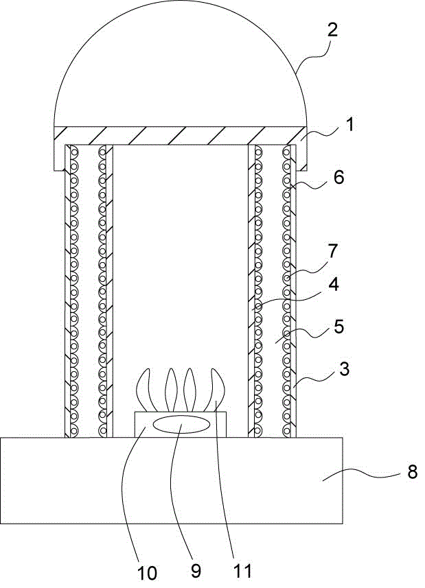
[0012] Such as figure 1 As shown, the present invention includes a paint bucket body, the top of the paint bucket body is movably connected with a top cover 1, a handle 2 is arranged above the paint bucket body, and the paint bucket body includes a metal outer layer 3, a metal inner layer 4 and a metal The polyurethane foam layer 5 between the outer layer 3 and the metal inner layer 4, the surface of the polyurethane foam layer 5 is provided with a groove 6, and the groove 6 is filled with phase change microcapsules 7, and a stirring device is arranged in the paint bucket body, and the paint bucket The bottom end of the barrel body is in contact with the magnetic stirrer 8. The groove 6 of the polyurethane foam layer 5 is filled with the setting of phase change microcapsules 7, which can significantly improve the thermal insulation performance of the inner layer of the paint bucket, and has higher thermal insulation performance than ordinary single-layer paint buckets, ensurin...


PUM


Abstract

The invention relates to a heat-preservation paint barrel for casting. The heat-preservation paint barrel comprises a paint barrel body; the top of the paint barrel body is movably connected with a top cover; a lifting handle is arranged at the upper side of the paint barrel body; the paint barrel body comprises a metal outer layer, a metal inner layer and a polyurethane foam layer arranged between the metal outer layer and the metal inner layer; a groove is formed in the surface of the polyurethane foam layer; the groove is internally filled with a phase-change microcapsule; a stirring device is arranged in the paint barrel body; the bottom of the paint barrel body is in contact connection with a magnetic stirrer. The heat-preservation paint barrel for casting is simple in structure, convenient to use and good in stirring effect, and can realize long-time effective heat preservation.

Description

technical field [0001] The invention relates to the technical field of casting equipment, in particular to a thermal insulation paint bucket for casting. Background technique [0002] The paint produced by the paint production line can be divided into cold paint and hot paint. Both cold paint and hot paint need to maintain a certain temperature for the supply of materials in the next process. The paint and hot paint are used for heat preservation separately. The traditional paint insulation barrel includes a barrel body and a lid covering the mouth of the barrel. The barrel body includes an inner wall and an outer wall covering the inner wall. There is a vacuum between the inner wall and the outer wall, and the vacuum layer ensures that the paint The temperature of the heat preservation barrel, the heat preservation effect of the paint heat preservation barrel of this structure is not ideal, is not conducive to the long-term effective heat preservation of the paint. [0003...

Claims


Application Information

Patent Timeline
Patent Type & Authority Applications(China)
IPC IPC(8): B01F7/26B01F13/08B01F15/06B01F27/93
CPCB01F27/93B01F33/453B01F35/51B01F35/90B01F2101/30
Inventor 娄土岭
Owner 娄土岭
Learn More