Sewage treatment anaerobic reaction system and water treatment method

An anaerobic reaction and sewage treatment technology, which is applied in the field of water treatment to achieve the effect of increasing the decomposition rate, increasing the area of ​​the separation zone, and achieving obvious effects.

Pending Publication Date: 2016-12-21
北京华夏大禹科技有限公司
View PDF10 Cites 8 Cited by
  • Summary
  • Abstract
  • Description
  • Claims
  • Application Information

AI Technical Summary

Problems solved by technology

[0021] The technical problem to be solved by the present invention is to provide a simple structure that can solve the problem that the area requirements of the anaerobic tank reaction zone and the sedimentation separation zone in the traditional anaerobic reactor containing a three-phase separator are...

Method used


Image

  • Sewage treatment anaerobic reaction system and water treatment method
  • Sewage treatment anaerobic reaction system and water treatment method
  • Sewage treatment anaerobic reaction system and water treatment method

Examples


Embodiment 1

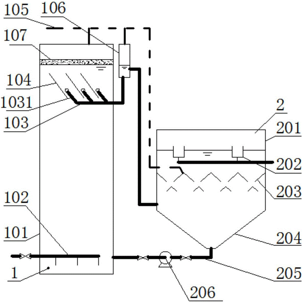
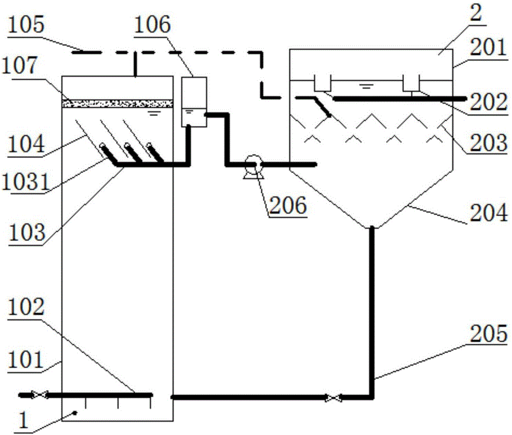
[0078] Such as figure 1 As shown, the present embodiment provides a sewage treatment anaerobic reaction system, comprising:

[0079] An anaerobic reaction tank 1 and a three-phase separation tank 2 provided separately, the water outlet of the anaerobic reaction tank 1 and the water inlet of the three-phase separation tank 2 are connected by a pipeline;

[0080] Anaerobic reaction tank 1 comprises anaerobic reaction tank body 101, water inlet system 102, water collection system 103 and biogas pipe 105, water inlet system 102 is arranged on the bottom in anaerobic reaction tank body 101, water collection system 103 is arranged In the middle and upper part of the anaerobic reaction pool body 101, the biogas pipe 105 is arranged on the top of the anaerobic reaction pool body 101;

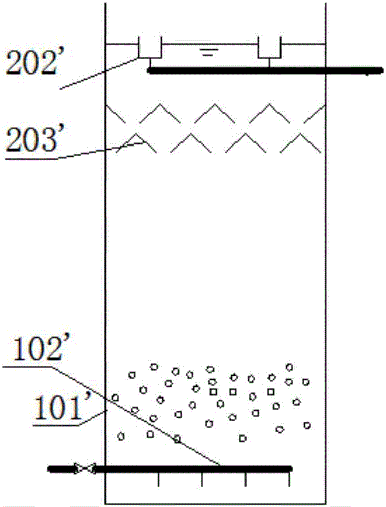
[0081] Three-phase separation tank 2 comprises three-phase separation tank body 201, outlet weir 202, three-phase separator 203, sludge bucket 204, and outlet weir 202 is arranged on the top in three-p...

Embodiment 2

[0103] Such as figure 2 As shown, the difference between this embodiment and embodiment 1 is:

[0104] The setting elevation of the three-phase separation tank 2 that provides the sewage treatment anaerobic reaction system in embodiment 2 is higher than the setting elevation of the anaerobic reaction tank 1, therefore, the effluent of the anaerobic reaction tank 1 needs to be arranged in the anaerobic reaction tank The lift pump 206 on the pipeline between the outlet of the three-phase separation tank 2 and the water inlet of the three-phase separation tank 2 is lifted to the three-phase separation tank 2, and the sludge in the sludge hopper 204 can flow to the drain by gravity through the sludge return system 205 In the oxygen reaction tank 1 , the final outlet water is also discharged from the system through the outlet weir 202 .

[0105] Therefore, structurally, the lift pump 206 in this embodiment is arranged on the pipeline between the water outlet of the anaerobic reac...


PUM


Abstract

The invention provides a sewage treatment anaerobic reaction system and a water treatment method. The sewage treatment anaerobic reaction system comprises an anaerobic reaction tank and a three-phase separation tank which are separately arranged. The anaerobic reaction tank comprises an anaerobic reaction tank body, a water inflow system and a water collecting system. The three-phase separation tank comprises a three-phase separation tank body, an effluent weir, a three-phase separator and a sludge hopper. The three-phase separator is arranged below the effluent weir, the sludge hopper is arranged at the bottom of the three-phase separation tank and connected with a sludge backflow system, and the sludge backflow system is connected with the anaerobic reaction tank. The invention further provides the water treatment method of the sewage treatment anaerobic reaction system. The problem that the area requirements of a reaction region and a precipitation separation region in a traditional anaerobic reactor are antagonistic and contradictory can be solved, and the system is simple in structure, convenient to maintain and good in sewage treatment effect; the sewage treatment anaerobic reaction system and the water treatment method are especially suitable for treating sewage, with the COD smaller than 5,000 ppm or the animal and vegetable oil content larger than 100 ppm, of slaughtered products and dairy products.

Description

technical field [0001] The invention relates to an anaerobic reaction system and a water treatment method for sewage treatment, in particular to an anaerobic reaction system and a water treatment method suitable for biological sewage / wastewater treatment of low-concentration waste water or oily waste water such as slaughtering and dairy products, and belongs to the water treatment method. Dealing with technical fields. Background technique [0002] There are several existing anaerobic technologies for biological treatment of sewage / wastewater: [0003] The earliest anaerobic process is the anaerobic filter process, which is equipped with fillers for filtration. This method can easily cause blockage of the anaerobic filter and is difficult to maintain. It is only suitable for small-scale water treatment. [0004] The anaerobic process that appeared later has anaerobic contact method, that is, a reaction tank is set in the front of the anaerobic tank, and a sedimentation tank...

Claims


Application Information

Patent Timeline
IPC IPC(8): C02F3/28
CPCC02F3/28C02F3/2866C02F3/2893C02F2209/42C02F2301/046C02F2209/08C02F2103/327C02F2103/22Y02W10/37Y02E50/30
Inventor 于容朴姚杰宇
Owner 北京华夏大禹科技有限公司
Why Eureka
Try Eureka