
a dyeing device

A technology of dyeing device and dyeing vat, which is applied in the field of dyeing, can solve problems such as complex structure, achieve high recovery efficiency, optimize denitrification and denitrification effect, and simple structure

Active Publication Date: 2018-07-10
浙江华昌新材料股份有限公司
View PDF5 Cites 2 Cited by
  • Summary
  • Abstract
  • Description
  • Claims
  • Application Information

AI Technical Summary

Problems solved by technology

Although this patent can realize the recovery of dye liquor, the overall operation is located outside the dye vat, and the dye liquor does not flow back directly to the dye vat, and the structure is relatively complicated

Method used


Image

  • a dyeing device
  • a dyeing device
  • a dyeing device

Examples


Embodiment Construction

[0027] The following are specific embodiments of the present invention and in conjunction with the accompanying drawings, the technical solutions of the present invention are further described, but the present invention is not limited to these embodiments.

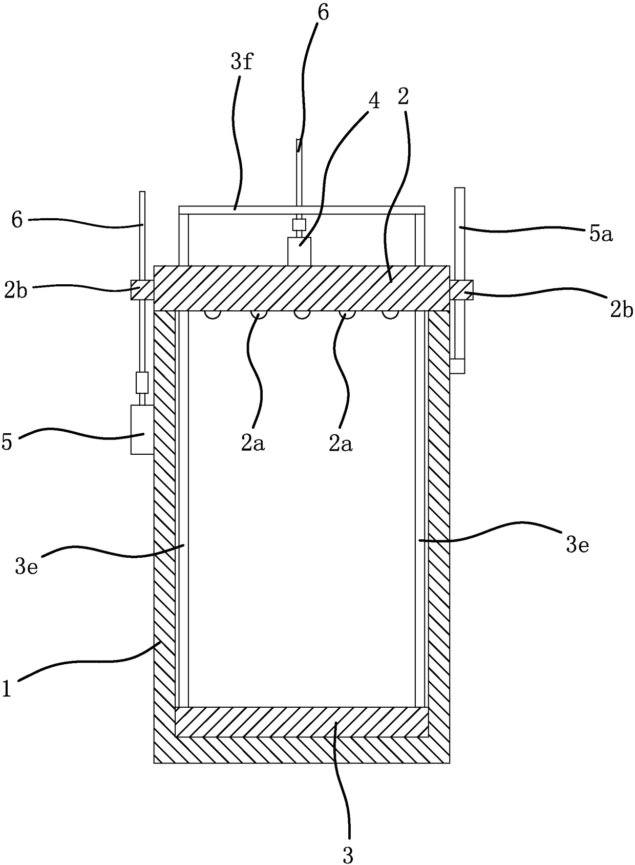
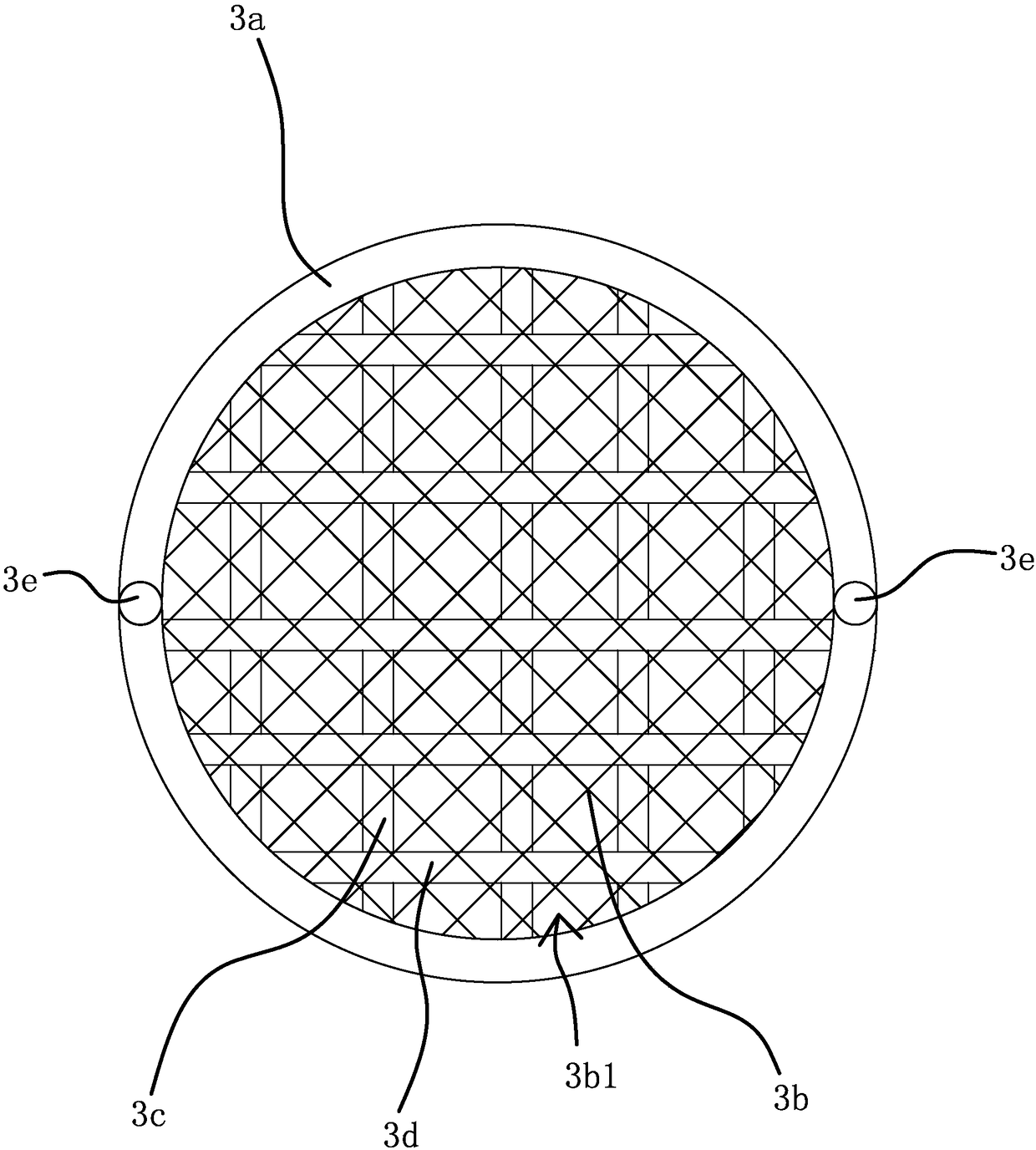
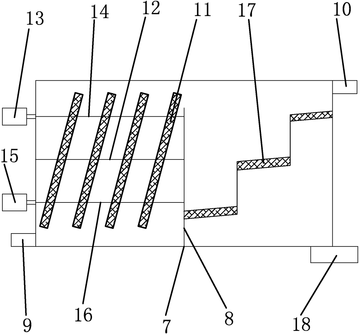
[0028] Such as figure 1 , figure 2 As shown, a dyeing device includes a dyeing vat, the dyeing vat includes a cylinder body 1 and a cylinder cover 2, a lifting plate 3 is provided in the cylinder body 1, a number of water filter holes 3b1 are provided on the lifting plate 3, and a lifting plate 3 is fixed with Two lifting rods 3e, the lifting rods 3e pass through the cylinder head 2, one end of the two lifting rods 3e passing through the cylinder head 2 is fixed by the connecting rod 3f, the lifting motor 4 is fixed on the cylinder head 2, and the lifting motor 4 is connected with a wire Rod 6, screw mandrel 6 vertically passes through the middle part of connecting rod 3f and is threadedly connected with connecting rod 3...


PUM

PropertyMeasurementUnit
thicknessaaaaaaaaaa
diameteraaaaaaaaaa
thicknessaaaaaaaaaa

Abstract

The invention provides a dyeing device and belongs to the technical field of shell fabrics. The dyeing device solves the problems in the prior art. The dyeing device comprises a dye vat. The dye vat comprises a vat body and a vat cover. The vat body is internally provided with a lifting plate. The lifting plate is provided with a plurality of water filtering holes. Two lifting rods are fixed to the lifting plate and penetrate out of the vat cover. The ends, penetrating out of the vat cover, of the two lifting rods are fixed through a connecting rod. A lifting motor is fixed to the vat cover and connected with a lead screw. The lead screw perpendicularly penetrates through the middle portion of the connecting rod and connected with the connecting rod through threads. The vat body is provided with a driving structure which can enable the vat cover to open or close the vat body. The vat body is further connected with a treating device for nitrogen removal by denitrification. The treating device for nitrogen removal by denitrification comprises a pool for nitrogen removal by denitrification, the pool for nitrogen removal by denitrification is internally divided into a reaction pool and a settling pool, a vertical partition plate is arranged between the reaction pool and the settling pool, and a circulation notch is formed in the top of the vertical partition plate.

Description

technical field [0001] The invention belongs to the technical field of dyeing, and relates to a dyeing device. Background technique [0002] The dyeing device mainly realizes dyeing by soaking the fabric in the dye vat, and dyeing the fabric through the dye liquor in the dye vat. After the dyeing is finished, the dyed fabric is taken out, and the current way is to directly take out the fabric and clean it by transferring the fabric through a barrel or the like. Because also have a lot of dye liquor on the fabric, directly fabric is taken out and cleaned and must cause unnecessary dye liquor on the fabric to be washed away, causes waste. [0003] In order to solve the above-mentioned problems, the Chinese patent literature discloses a padding device for dyeing vats. In this patent, the dyeing liquor is recovered through a padding machine located at the cloth outlet of the dyeing vat. Lifting series, lifting guide rail seat, lifting motor, drainage tank and other structures....

Claims


Application Information

Patent Timeline
Patent Type & Authority Patents(China)
IPC IPC(8): D06B23/14D06B23/20C02F9/00
CPCC02F1/001C02F1/50C02F1/5236C02F1/56C02F3/02C02F3/28C02F3/301C02F9/00C02F2001/007D06B23/14D06B23/20
Inventor 戚小华
Owner 浙江华昌新材料股份有限公司
Learn More