
Renewable energy free piston type linear generator

A linear generator and regenerative energy technology, applied in the field of renewable energy free-piston linear generators, can solve problems such as resource shortage, damage to the environment and human health, and achieve the effect of reducing quantity and weight and ensuring long-distance cruising range requirements.

Inactive Publication Date: 2016-12-21
裘根富
View PDF0 Cites 4 Cited by
  • Summary
  • Abstract
  • Description
  • Claims
  • Application Information

AI Technical Summary

Problems solved by technology

[0002] The accompanying energy security issues and environmental pollution issues are the two most thorny bottleneck issues. Petroleum security, resource shortage, and harmful substances emitted by automobiles when driving exhaust damage the environment and human health. There is an urgent need for a renewable new energy to replace petroleum energy. , in order to overcome the deficiencies in the energy security and environmental pollution of the existing means of transportation

Method used


Image

  • Renewable energy free piston type linear generator
  • Renewable energy free piston type linear generator
  • Renewable energy free piston type linear generator

Examples


Embodiment 1

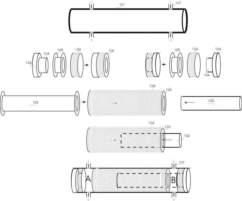
[0047] like figure 1 When the shown renewable energy free piston type linear generator includes the top dead center of the permanent magnet double-headed piston 102, the repulsive potential energy of the permanent magnet double-headed piston 102 and the electric permanent magnet 104 with the same polarity bounces back to the permanent magnet double-headed piston. The head piston 102 moves to the bottom dead center (corresponding to the top dead center position of the segmented cylinder) through the inertia of the ball bearing and the resultant force of the compressed air, and the permanent magnet double-headed piston 102 rebounds to the top dead center position on the same principle to complete a Stroke, the permanent magnet double-headed piston 102 reciprocates to do work in the A and B segmented cylinders, cutting the magnetic field lines to generate electric energy and thermal energy of the induced current, and the electronic throttle valve 107 and the intake manifold 207, e...

Embodiment 2

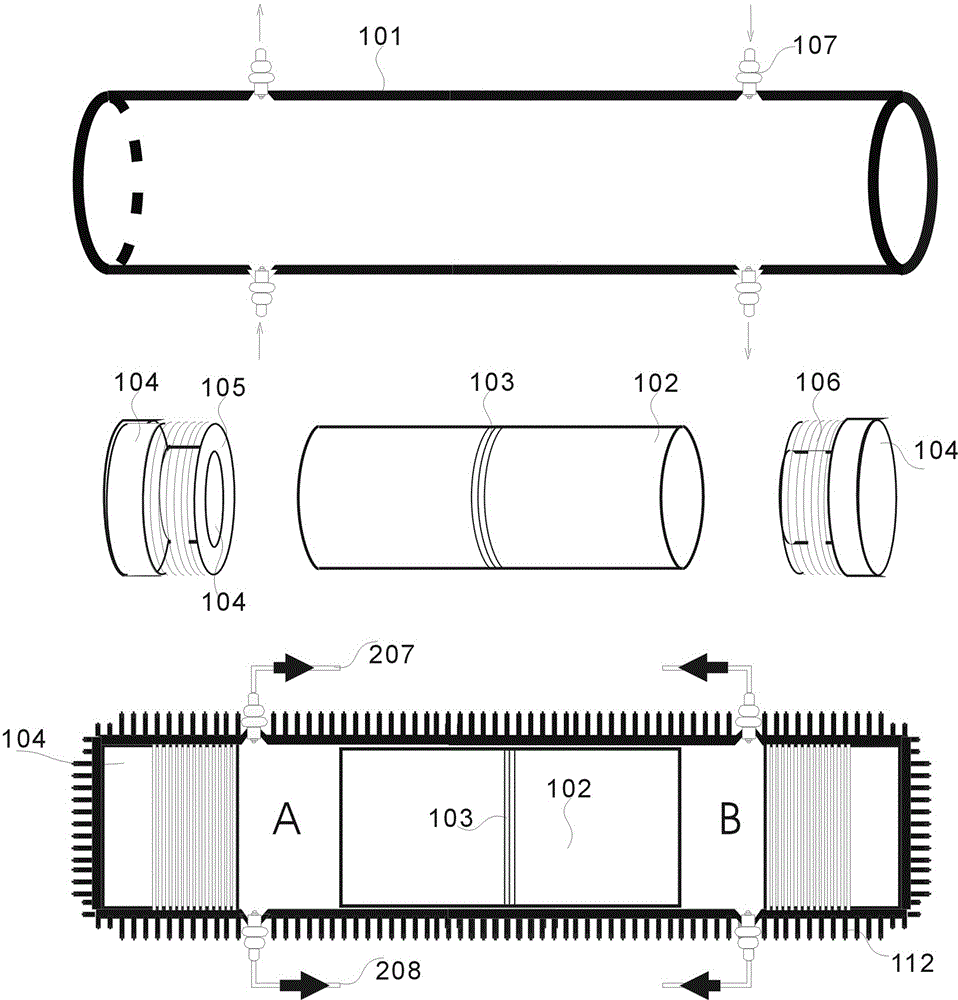
[0049] like figure 2 The difference between the shown renewable energy free-piston linear generator and Embodiment 1 is that an automatic pneumatic spring valve 108 is set on the cylinder wall, and there is no central permanent magnet double-headed piston 102. The resin coil on the cylinder liner 105 and induction coil 106.

Embodiment 3

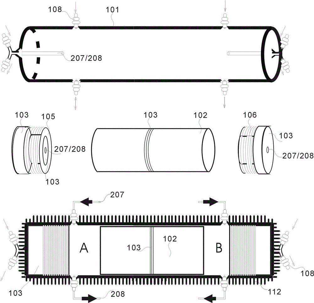
[0051] like image 3 The difference between the shown renewable energy free-piston linear generator and Embodiment 1 is that an automatic pneumatic spring valve 108 is set on the cylinder wall and on the top of the cylinder, and an intake manifold 207 and an exhaust gas valve are set on the top of the cylinder. Manifold 208, resin coil 105 and induction coil 106 on double-headed piston 102 cylinder liner without intermediate permanent magnet.


PUM


Abstract

A renewable energy free piston type linear generator, using the repulsive potential energy of the same polarity of NdFeB permanent magnets to replace a method, method and structure for the explosion of cylinder oil to push the piston to move, including electric permanent magnets installed at both ends of the cylinder The magnet and the central permanent magnet double-headed piston divide the cylinder into two independent A and B segmented cylinders. The electric permanent magnet becomes the rebound mechanism, and the intake and exhaust manifolds are equipped with turbocharging devices for permanent magnet double-headed The piston runs at idle speed and at the top dead center, under the action of the repulsive potential energy of the double-headed piston of the permanent magnet and the magnetic pole of the electropermanent magnet and the combined force of the air pressure, the left and right reciprocating motions in the A and B segmented cylinders cut the magnetic induction line to generate an induced current. Electricity and heat.

Description

technical field [0001] The invention relates to the field of new energy technology, which converts the repulsive potential energy of the same polarity of NdFeB permanent magnets into heat energy and electric energy, and particularly relates to a car with a renewable energy free piston type linear generator, which becomes a real-time renewable transportation tool The advanced power supply system, whose power meets all the energy consumption of transportation vehicles, provides basic technical support for the realization of long-distance cruising range, and achieves the purpose of traveling around the world. Background technique [0002] The accompanying energy security issues and environmental pollution issues are the two most difficult bottleneck issues. Petroleum security, resource shortage, and harmful substances emitted by the exhaust gas of automobiles when driving damage the environment and human health. There is an urgent need for a renewable new energy to replace petro...

Claims


Application Information

Patent Timeline
IPC IPC(8): F01B11/00F01B23/10H02J7/32
CPCF01B11/002F01B23/10H02J7/32
Inventor 裘根富
Owner 裘根富
Learn More