Relay generator

A generator and relay-type technology, applied in battery circuit devices, current collectors, electromechanical devices, etc., can solve problems such as damage to the environment, human health, and resource constraints

Inactive Publication Date: 2018-08-21
裘根富
View PDF0 Cites 2 Cited by
  • Summary
  • Abstract
  • Description
  • Claims
  • Application Information

AI Technical Summary

Problems solved by technology

[0002] The accompanying energy security issues and environmental pollution issues are the two most thorny bottleneck issues. Petroleum security, resource shortage, and harmful substances emitted by automobiles when driving exhaust damage the environment and human health. There is an urgent need for a renewable new energy to replace petroleum energy. , in order to overcome the deficiencies in the energy security and environmental pollution of the existing means of transportation

Method used


Image

  • Relay generator
  • Relay generator
  • Relay generator

Examples


Embodiment 1

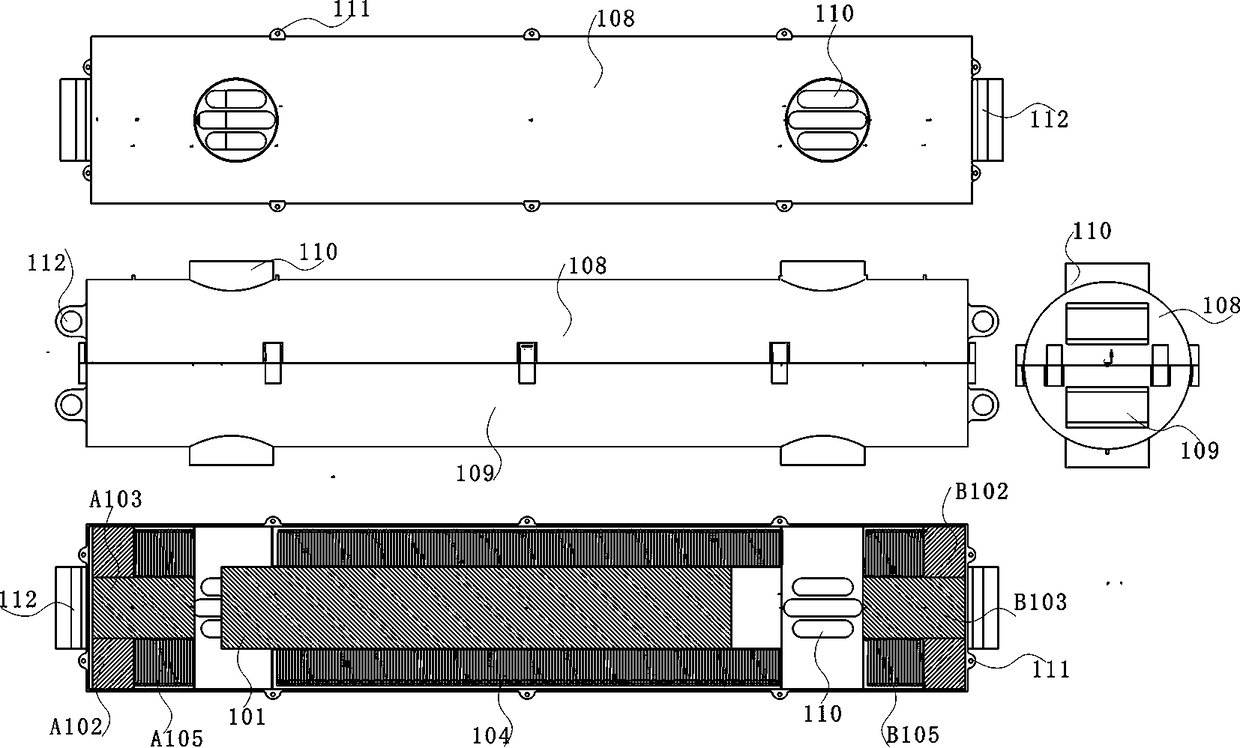
[0059] Example 1 figure 1 .

[0060] In some embodiments, the body further includes: a cylinder head 108, a cylinder head gasket, a cylinder block 109, and a cylinder liner. Electromagnets and a central permanent magnet piston 101 are arranged at both ends of the cylinder to separate the cylinder into two independent cylinders. The A and B segmented cylinders are equipped with intake and exhaust window vanes 110 connected to the intake and exhaust pipes on the cylinder wall, and are used for the intake and exhaust required for the permanent magnet piston 101 to move; the cylinder block 109 is a horizontal pair Opposite cylinders, cylindrical upper and lower axial split structures, the body is fastened by screws, and the two ends are provided with mounting earrings 112 holes, which are made of aluminum-magnesium alloy and 304 stainless steel; the body has receiving electromagnets and resin coils 106 , the bore of the induction coil 105 and the induction coil 104, the shape of ...

Embodiment 2

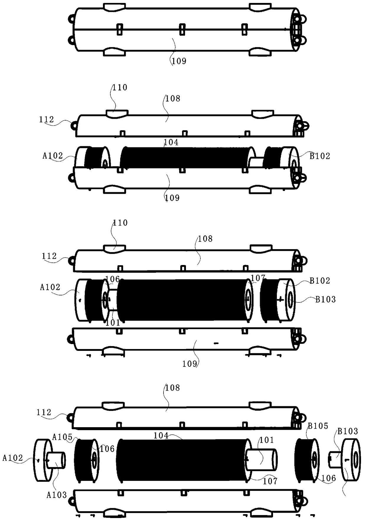
[0066] Example 2 figure 2 .

[0067] In some embodiments, where figure 2 The exploded diagram, the working process of the relationship between the assembly base and each part is as follows: when installing, the cylinder block 109 is placed at the bottom, the intake and exhaust vanes 110 are vertically downward, and the cylinder head 108 is placed on the top; the permanent magnet A102 is coaxial with the electromagnet core A103 And tangent to form a horseshoe structure, the resin coil 106 is wound with an enameled wire to form an induction coil A105, and the two are combined to form an A cylinder electromagnet, which is coaxial and tangent to the inner wall of the cylinder and the rib groove; the permanent magnet B102 and the electromagnet core B103 is coaxial and tangent to form a horseshoe-shaped structure. The resin coil 106 is wound with enameled wire to form an induction coil B105. The two are combined to form a B cylinder electromagnet, which is coaxial and tangent to ...

Embodiment 3

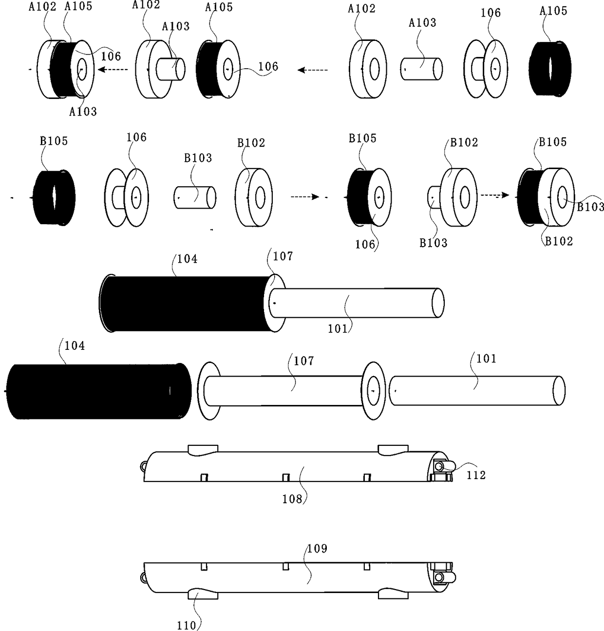
[0068] Example 3 image 3 .

[0069] In some embodiments, where assembly parts image 3 Isometric diagram, the electromagnet includes: permanent magnet A102, electromagnet core A103, induction coil A105, resin wire reel 106 to form A segmented cylinder electromagnet; permanent magnet B102, electromagnet core B103, induction coil B105, resin wire reel 106 , Constitute the B-section cylinder electromagnet, the electromagnet is used for the control mechanism that the permanent magnet piston 101 repels and attracts each other.

[0070] In some embodiments, the permanent magnet A102 and the permanent magnet B102 are made of neodymium iron boron, and the shape is flat and hollow, and the surface layer is coated with ceramics to increase oxidation resistance; the material of the electromagnet core A103 and the electromagnet core B103 is soft iron , which is in the form of a horseshoe structure formed of a cylindrical shape and a permanent magnet 102, and the surface layer is coated...


PUM


Abstract

The invention relates to a relay generator, which is characterized in that a cylinder is provided with electromagnets at two ends and a permanent magnet piston at the middle, the cylinder is separatedinto two independent segmented cylinders A, B, the permanent magnet piston is driven to move and do work by using the electromagnets to generate potential energy of mutual exclusion of magnetic polesof the same polarity and mutual attraction of magnetic poles of different polarities, magnetic induction lines cut induction coils to generate induction current, and the generated induction current is far higher than the energy consumption of the driving of the electromagnets. Therefore, the generator is innovative, the exclusion and attraction potential energy of the permanent magnets is a kindof renewable energy which can be reused, part of the current generated by the generator flows back to the electromagnets for driving, and part of the current is used for loads and energy storage, so that the generator has a capacity of continuously outputting the current.

Description

technical field [0001] The invention relates to the technical field of new energy generators and electric energy amplification. An electromagnet is used to drive a permanent magnet piston to generate potential energy in which magnetic poles of the same name repel each other and magnetic poles of different names attract each other. And thermal energy, especially involving a relay generator, has become a real-time renewable power supply system for transportation, providing a basic technical guarantee for the long-distance cruising range of pure electric vehicles. Background technique [0002] The accompanying energy security issues and environmental pollution issues are the two most difficult bottleneck issues. Petroleum security, resource shortage, and harmful substances emitted by the exhaust gas of automobiles when driving damage the environment and human health. There is an urgent need for a renewable new energy to replace petroleum energy. , to overcome the deficiencies i...

Claims


Application Information

Patent Timeline
IPC IPC(8): H02K7/18H02J7/14H02J7/32
CPCH02J7/1415H02J7/32H02K7/1815
Inventor 裘根富
Owner 裘根富
Why Eureka
Try Eureka