Method for manufacturing blading member assembly, and blading member assembly

A technology of components and blades, applied in the field of blade components, can solve the problems of impossibility of manufacturing cooling holes, such as through drilling, complexity, poor coating quality, etc., to achieve excellent accessibility, fast processing, and good coating thickness Effect

Inactive Publication Date: 2016-12-21
ANSALDO ENERGIA IP UK LTD
View PDF9 Cites 1 Cited by
  • Summary
  • Abstract
  • Description
  • Claims
  • Application Information

AI Technical Summary

Problems solved by technology

In other words, this means that if, for example, the cooling hole of an airfoil is intended to be arranged such that its extension on the outside of the airfoil will intersect the platform or another airfoil, such a cooling hole is not possible, for example, by drilling holes, or, if at all possible, only possible with specially designed complex and expensive tools and methods
[0005] Furthermore, when applying coatings to blade components, it can be considered complex if it is not possible to reliably and controllably apply the coating to such dead spaces
Specifically, the need to coat the platform and the airfoil at the same time can lead to overspray in the chamfer, which in turn leads to poor coating quality

Method used


Image

  • Method for manufacturing blading member assembly, and blading member assembly
  • Method for manufacturing blading member assembly, and blading member assembly
  • Method for manufacturing blading member assembly, and blading member assembly

Examples


Embodiment Construction

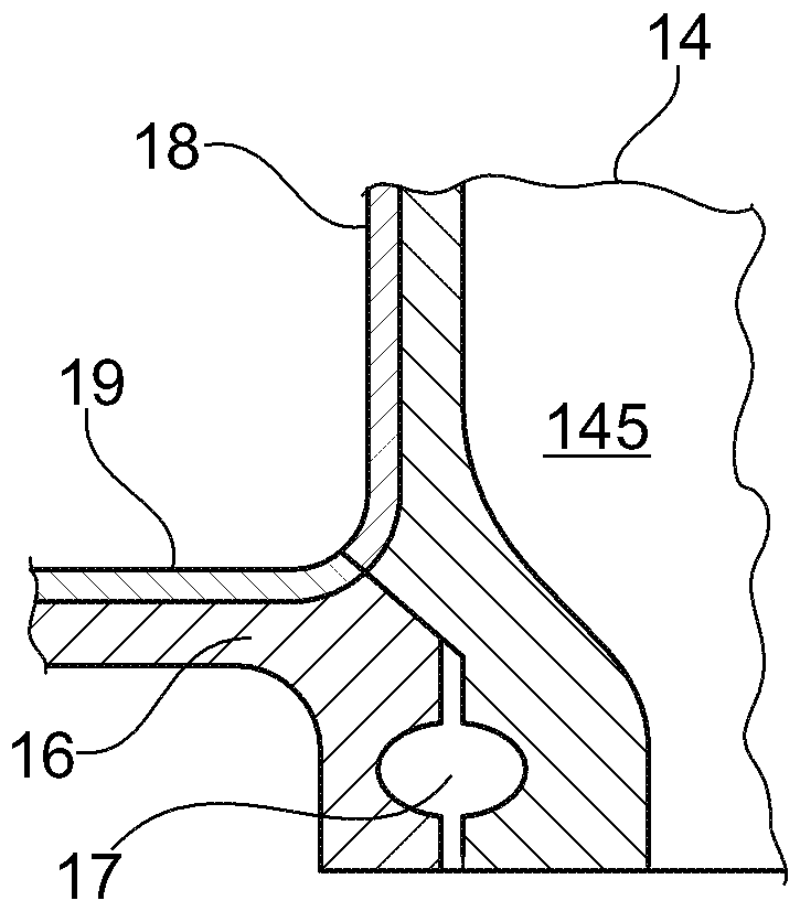
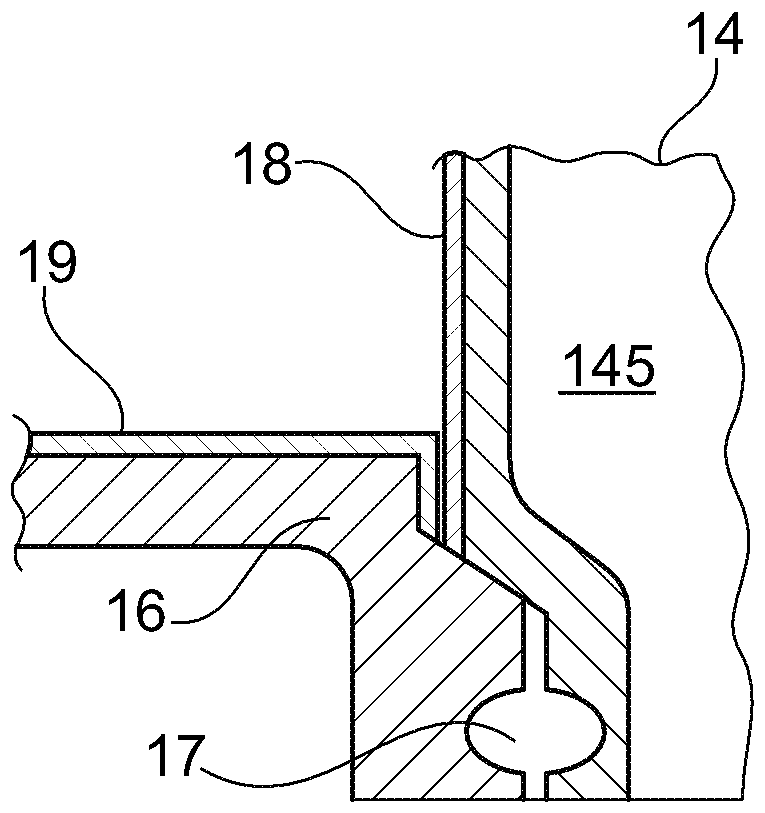
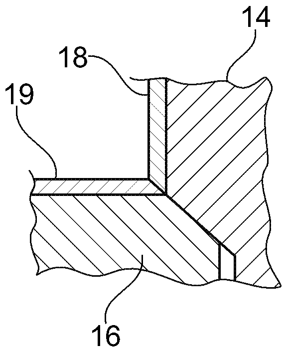
[0069] figure 1 The problem on which the subject matter of the present disclosure is based is depicted for informational purposes only. A blade part 1 is shown comprising an airfoil 11 , a first platform 12 and a second platform 13 . As will be readily understood, the outer surface of the airfoil 11 and the airfoil-facing surfaces of the platforms 12 , 13 constitute parts intended to be exposed to the working gas flow, or in short, to the hot gas side of the blade part 1 . surface. In the present description, it is shown how cooling openings are produced eg in an airfoil 11 . The tool spindle 2 is used to carry tools for producing cooling openings, such as drills, etching tools or laser sources. As can be seen, the tool spindle 2 interferes with the platform 13 when used to produce cooling openings in the airfoil 11 . The interference limits the ability to make cooling openings at required locations and at required angles relative to the surface of the airfoil 11 . Obviou...


PUM


Abstract

Disclosed is a method for manufacturing a blading member assembly (10) for a fluid flow machine, wherein the blading member assembly includes at least one airfoil member (14) and one platform member (16). The method includes manufacturing a platform member blank, manufacturing an airfoil member blank, and processing at least one of said blanks thus obtaining the at least one airfoil member and at least one platform member, and subsequently joining the at least one platform member and the at least one airfoil member, thus providing the blading member assembly. The method, for instance, provides larger flexibility in arranging cooling openings (144).

Description

technical field [0001] The present disclosure relates to a method for manufacturing a blade part assembly as described in claim 1 . It also relates to a blade part assembly as described in any one of the device claims. In particular, the blade part is manufactured by the method mentioned initially. Background technique [0002] Blade components for fluid flow machines may require extensive processing after blade component blanks have been obtained, eg by casting, selective laser melting, selective electron beam melting or any other suitable method. In gas turbines in particular, blades may be exposed to a complex environment including gases at elevated temperatures (which may even exceed the melting temperature of the applied materials) and intruding hot combustion gases. It is therefore known to apply protective and / or thermal barrier coatings to blade components. It is also known to provide cooling holes, or more generally cooling openings, in blade parts, such as to ap...

Claims


Application Information

Patent Timeline
Patent Type & Authority Applications(China)
IPC IPC(8): F01D5/12B23P15/00
CPCB23P15/00F01D5/12B23P15/04F01D5/288F01D9/042F01D9/065F05D2240/81F05D2260/202F01D5/186F05D2230/10F05D2230/60F05D2230/90F05D2220/32
Inventor H.布兰德E.本兹R.霍伊恩科I.帕拉里卡斯
Owner ANSALDO ENERGIA IP UK LTD
Why Eureka
Try Eureka