A Lissajous device based on the principle of electro-optic modulation of optical crystal refractive index distribution

A technology of refractive index distribution and electro-optic modulation, applied in optics, nonlinear optics, instruments, etc., can solve the problems of rough and time-consuming adjustment of mirrors, inconvenient secondary use, and poor repeatability, and achieve multi-directional modulation of beams. Low loss and good stability

Active Publication Date: 2019-02-26
HARBIN ENG UNIV
View PDF4 Cites 0 Cited by
  • Summary
  • Abstract
  • Description
  • Claims
  • Application Information

AI Technical Summary

Problems solved by technology

3. Laser Lissajous demonstrator: The experimental principle of this method is to use the principle of laser light rods to realize Lissajous figures through mirrors, but the folded optical path also takes up a large space, the optical path is folded, the repeatability is poor, the frequency is low, and the reflection The adjustment of the mirror is rough and time-consuming, and the secondary use is very inconvenient

Method used


Image

  • A Lissajous device based on the principle of electro-optic modulation of optical crystal refractive index distribution
  • A Lissajous device based on the principle of electro-optic modulation of optical crystal refractive index distribution
  • A Lissajous device based on the principle of electro-optic modulation of optical crystal refractive index distribution

Examples


Embodiment 1

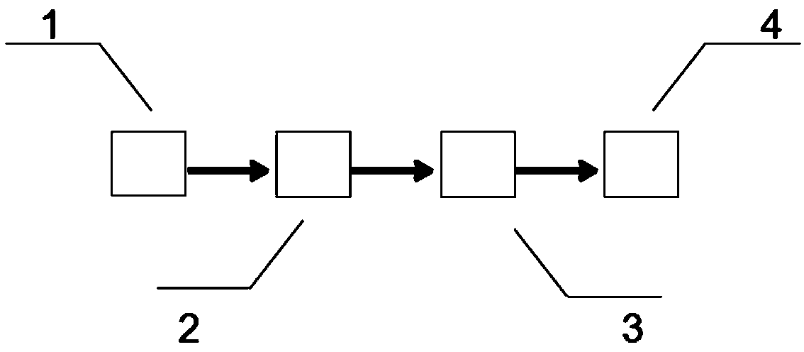
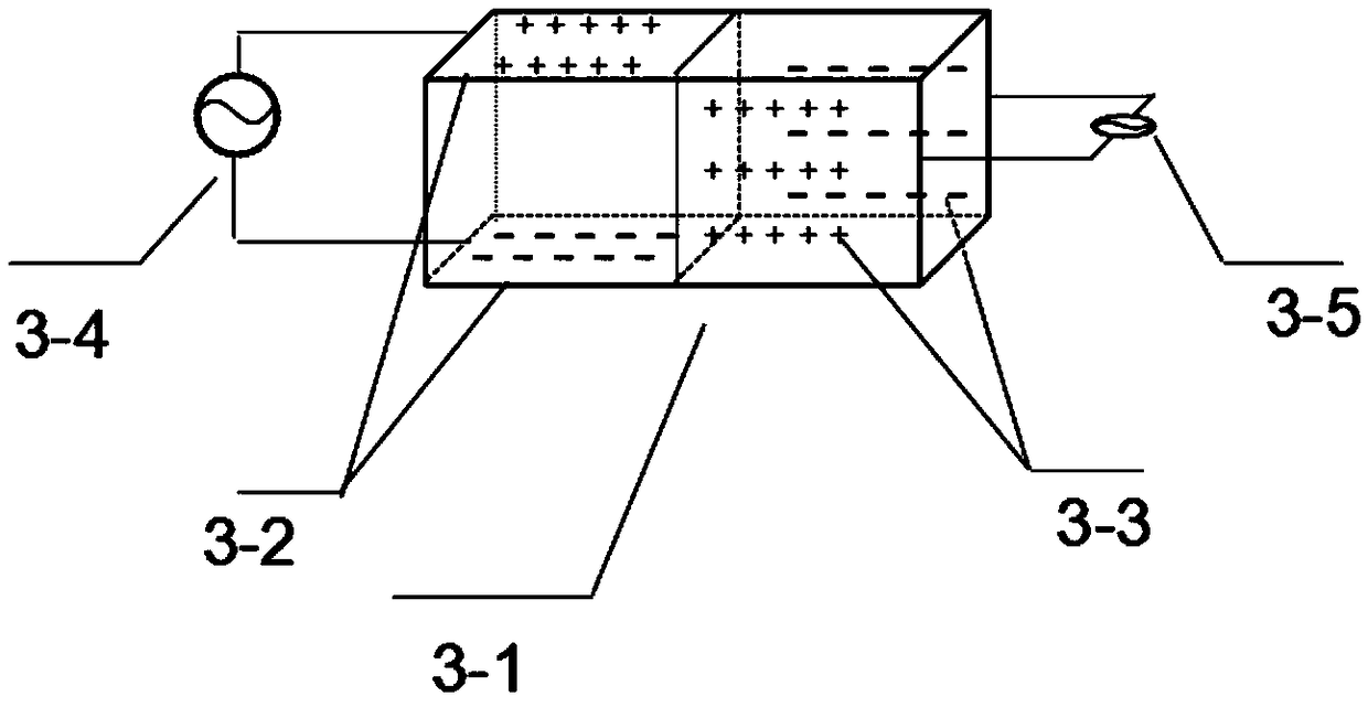
[0013] Embodiment 1: A novel Lissajous device based on the principle of electro-optic modulation of optical crystal refractive index distribution, consisting of a laser, a beam collimator, an electro-optic modulation unit, and a CCD image sensor. The KTN crystal is processed into a cuboid structure, and a metal plate electrode is prepared by a coating process, and two pairs of plate electrodes are placed on the side of the crystal, as shown in the attached figure 2 shown. Each pair of plate electrodes is respectively connected to an external modulation voltage source, and each voltage source is respectively subjected to sine and cosine modulation. After the incident beam is modulated by the KTN crystal, the outgoing beam track is received by the CCD image sensor.

[0014] The electro-optic modulation unit is composed of a KTN crystal 3-1, two pairs of plate electrodes 3-2, 3-3, and modulation voltage sources 3-4, 3-5.

[0015] The two pairs of plate electrodes 3-2, 3-3 are r...

Embodiment 2

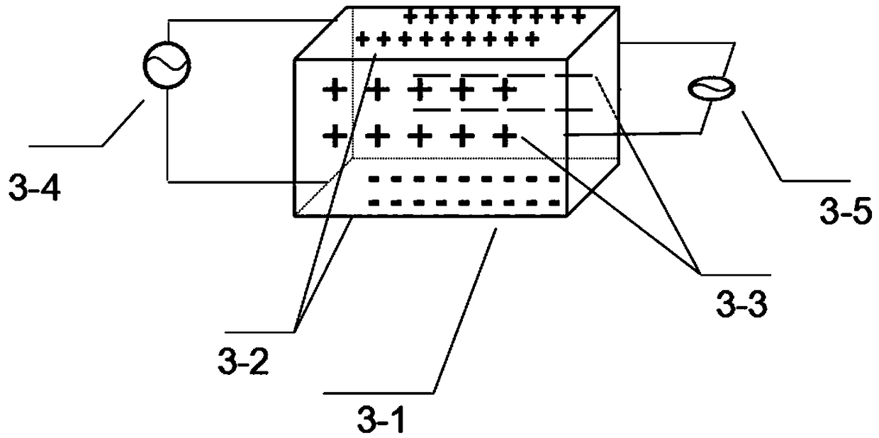
[0017] Embodiment 2: A novel Lissajous device based on the principle of electro-optic modulation of optical crystal refractive index distribution, consisting of a laser, a beam collimator, an electro-optic modulation unit, and a CCD image sensor. The KTN crystal is processed into a cuboid structure, and a metal plate electrode is prepared by a coating process, and two pairs of plate electrodes are placed on the side of the crystal, as shown in the attached image 3 shown. Each pair of plate electrodes is respectively connected to an external modulation voltage source, and each voltage source is respectively subjected to sine and cosine modulation. After the incident beam is modulated by the KTN crystal, the outgoing beam track is received by the CCD image sensor.

[0018] The electro-optic modulation unit is composed of a KTN crystal 3-1, two pairs of plate electrodes 3-2, 3-3, and modulation voltage sources 3-4, 3-5.

[0019] The two pairs of plate electrodes 3-2, 3-3 are r...


PUM


Abstract

The invention relates to a lissajous device based on the optical crystal refractive index profile electro-optical modulation principle. The lissajous device comprises a laser device, a beam collimator, an electro-optical modulation unit and a CCD image sensor, KTN crystal is processed into a cuboid structure, metal plate electrodes are prepared through a coating technology, the two pairs of plate electrodes are arranged on the side face of the crystal, each pair of plate electrodes is connected with an external modulation voltage source, and sine and cosine modulation is carried out on each modulation voltage source; after an incident beam is modulated through the KTN crystal, and emergent beam track is received by the CCD image sensor. The device has the advantages of adopting single beam operation, dispensing with a folded path and being free of mechanical vibration, low in space loss, large in frequency dynamic modulation range, capable of being manipulated at high accuracy, high in device integration level and stability and capable of modulating the beam in a multi-direction mode.

Description

technical field [0001] The invention relates to a Lissajous device based on the principle of electro-optical modulation of optical crystal refractive index distribution Background technique [0002] The Lissajous figure refers to a regular and stable closed curve family composed of two simple harmonic vibrations with simple integer ratios in the perpendicular direction. Lissajous graphs are widely used in sensor dynamic characteristic detection, frequency measurement, engineering signal detection and so on. At present, the devices that produce Lissajous figures are: 1. Mechanical Lissajous demonstration instrument: the experimental principle of this device is to synthesize Lissajous figures by using mechanical vibrations driven by manual or electric motors. The disadvantage of this method is that it produces mechanical The vibration frequency control error is large, the loss is large, and the need for motors and other instruments takes up a lot of space. 2. Electrical sign...

Claims


Application Information

Patent Timeline
Patent Type & Authority Patents(China)
IPC IPC(8): G02F1/03
CPCG02F1/0305G02F1/0327
Inventor 李立张斌田凤军
Owner HARBIN ENG UNIV
Why Eureka
Try Eureka