

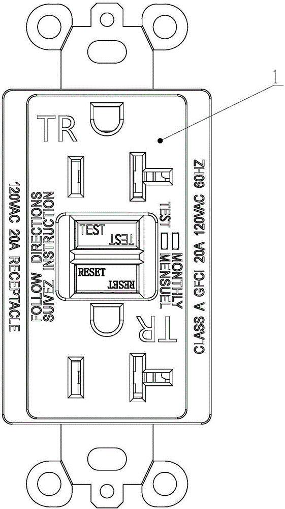
Electric leakage protection socket with function of reverse wiring protection
A technology of protection function and leakage protection, applied in emergency protection circuit devices, parts of protection switches, protective grounding/shielding devices of connecting parts, etc. To achieve the effect of reasonable and ingenious structure, stable and reliable action, smooth and reliable action
- Summary
- Abstract
- Description
- Claims
- Application Information
AI Technical Summary
Problems solved by technology
Method used
Image

Examples
Embodiment 1
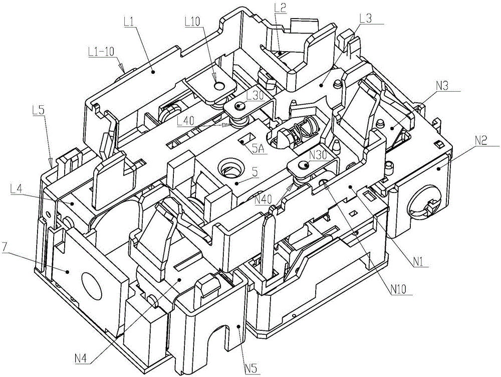
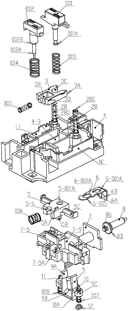
[0034] refer to Figure 1 to Figure 9 As shown, the earth leakage protection socket with reverse wiring protection function of the present invention includes main circuit switches (L10, L40) (L30, L40) (N10, N40) (N30, N40), middle bracket 4, reset button 001, off The buckle coil 7 and the electromagnetic tripping mechanism also include a lifter 9, and a metal rod 10, 11 is respectively set on both sides of the lifter 9C, and the lower ends of the metal rods 10, 11 are set with return springs 007, 008, and the upper ends of the pair of metal rods are connected correctly. In this state, it is in contact with the moving metal pieces (N4, L4) of the main circuit switch, and the return spring 008 of the neutral line metal rod 11 and a static metal piece K9 located below the zero line metal bar return spring 008 form a tripping coil 9 circuit In the reverse wiring path switch of normal close, the upper ends of the neutral wire metal rod 11 and the live wire metal rod 10 are kept in...
Embodiment 2
[0043] refer to Figure 3-1 The difference between this embodiment and Embodiment 1 is that the bottom of the middle bracket is open to form a sliding fitting area for the locking piece to be put in, and the middle bracket and the locking piece are combined to form a sliding limit through the combination of the convex nail 3D or the buckle plate mechanism. All the other structures are basically the same as the first embodiment. Convex nails are integrated on both sides of the locking piece.
Embodiment 3
[0045] refer to Figure 3-2 The difference between this embodiment and Embodiment 1 is that a cover plate is arranged above the locking member, and the cover plate has a through hole or a gap for the guide column of the reset button and the guide column of the test button to pass through. The bracket is hooked and positioned with a positioning convex nail, and above the positioning convex nail, there is a relief defect area that is convenient for snapping into the middle bracket. All the other structures are basically the same as the first embodiment.
PUM
 Abstract
Description
Claims
Application Information