Induction heating coil and heating method thereof

A technology of induction heating coils and heating methods, which is applied in the direction of induction heating, coil devices, electric heating devices, etc., can solve problems such as difficulty in ensuring brazing quality and uneven distribution of magnetic beams, and achieve brazing quality and short production cycles. Effect

Active Publication Date: 2016-12-21
PANASONIC INTELLECTUAL PROPERTY MANAGEMENT CO LTD
View PDF5 Cites 7 Cited by
  • Summary
  • Abstract
  • Description
  • Claims
  • Application Information

AI Technical Summary

Problems solved by technology

Furthermore, the distribution of the magnetic flux also becomes uneven, and in the case of brazing of aluminum whose melting point difference between the base material and the brazing material is very small, it is difficult to ensure the quality of the brazing by uniform heating.

Method used


Image

  • Induction heating coil and heating method thereof
  • Induction heating coil and heating method thereof
  • Induction heating coil and heating method thereof

Examples


no. 1 Embodiment approach

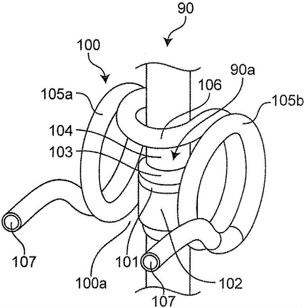
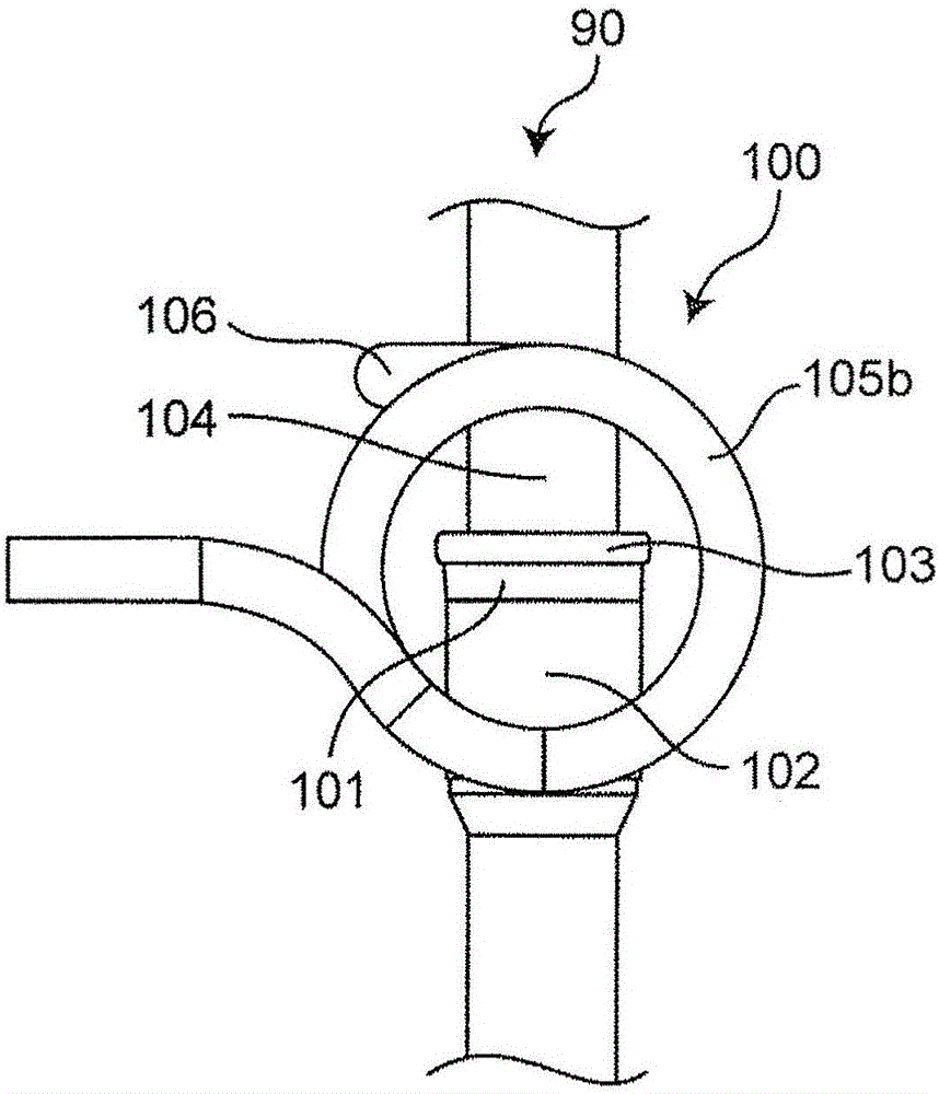
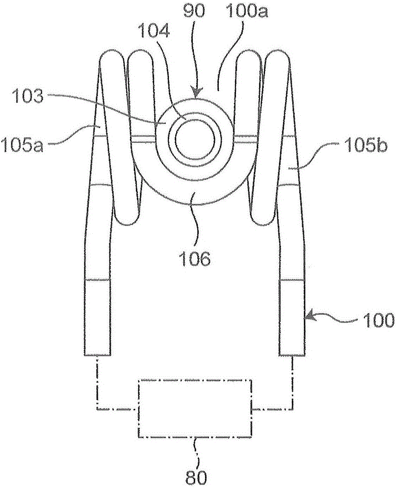
[0079] Figure 1A It is a diagram showing the structure of the induction heating device used in the heating method according to the first embodiment of the present invention, that is, the induction heating coil 100 for brazing the heat transfer pipe 102 and the joint pipe 104 which are two metal pipes . also, Figure 1B It is a configuration diagram of the induction heating coil 100 viewed from the side. Figure 1C It is a configuration diagram of the induction heating coil 100 viewed from above. Figure 1D It is a configuration diagram of the induction heating coil 100 viewed from the front. Figure 2A ~ Figure 2E It is an explanatory drawing showing each process of the joining method of the heat transfer pipe 102 which is two metal pipes, and the joint pipe 104 concerning 1st Embodiment of this invention.

[0080] The induction heating coil 100 arranges the brazing part 90a of the object to be heated 90 in the part to be heated (the space to be heated or the region to be...

no. 2 Embodiment approach

[0112] Figure 6A It is a configuration diagram of an induction heating coil 100B for brazing a heat transfer pipe 202 , which is a metal pipe, and a joint pipe 204 according to the second embodiment of the present invention. Figure 6B It is a configuration diagram viewed from the side of the induction heating coil 100B. Figure 6C It is a structural diagram seen from the back surface of the induction heating coil 100B. Figure 6D It is a configuration diagram viewed from above the induction heating coil 100B. As an example, the induction heating coil 100B is formed of a copper tube, and the cooling water 207 flows through the copper tube.

[0113] The induction heating coil 100B is largely different from the first embodiment in that the connecting portion 206 is arranged on the heating target portion 100Ba with respect to the end of the heat transfer pipe 202 as the first metal pipe and the joint pipe 204 as the second metal pipe. The ends and the brazing filler metal 203...


PUM

PropertyMeasurementUnit
diameteraaaaaaaaaa
thicknessaaaaaaaaaa
diameteraaaaaaaaaa

Abstract

The invention provides an induction heating coil and a heating method thereof. The induction heating coil and heating method have the advantages that on the basis that the heating efficiency is guaranteed, the uniform heating is realized, the production period is short, and the quality of braze welding is guaranteed. In the provided induction heating coil (100), high frequency I generated through electromagnetic induction. In the heating object part (100a), a braze material (103) is arranged on the joint part between the end part of a first metal pipe (102) and the end part of a second metal pipe (104), wherein the external diameter of the first metal pipe is greater than that of the second metal pipe. Braze welding is carried out through high frequency heating. Reeling parts (105a, 105b) with at least two coils are formed on two sides of the first metal pipe and the second metal pipe respectively in opposite directions. Moreover, the join part (106) that connects all reeling parts is arranged on a side more close to the second metal pipe relative to the first metal pipe.

Description

technical field [0001] The present invention relates to an induction heating coil and a heating method used for high-frequency brazing of metal pipes in heat exchangers used in air conditioners such as air conditioners. Background technique [0002] In recent years, from the viewpoint of global environmental protection, CO 2 The reduction of energy consumption is being strongly demanded, and energy saving has also become a major issue in air conditioners that account for about 25% of energy consumption in general households. In particular, among them, the heat exchanger is one of the important components of the air conditioner, and the demand for high performance is very high. [0003] Generally, it is known that a heat exchanger for an air conditioner is provided with a plurality of fins made of aluminum or iron arranged in parallel to each other, these fins are penetrated in the thickness direction, and a plurality of heat conduction fins are provided in the through holes...

Claims


Application Information

Patent Timeline
Patent Type & Authority Applications(China)
IPC IPC(8): H05B6/36B23K1/002B23K3/04
CPCB23K1/002B23K3/0475H05B6/36
Inventor 越智正三五闲学小岛俊之
Owner PANASONIC INTELLECTUAL PROPERTY MANAGEMENT CO LTD
Why Eureka
Try Eureka