Directional bobbin conveying device of bobbin arranging machine

A conveying device and horizontal conveying technology, applied in the direction of conveyor, conveyor objects, transportation and packaging, etc., can solve the problems of slow management and management, high production cost, high labor intensity, etc., to solve the problem of slow orientation speed and highlight the essence Sexual effect, the effect of increasing processing speed

Active Publication Date: 2016-12-28
ZHEJIANG ZILI MACHINERY
View PDF6 Cites 13 Cited by
  • Summary
  • Abstract
  • Description
  • Claims
  • Application Information

AI Technical Summary

Problems solved by technology

[0002] For the automatic winding machine used by textile enterprises, the yarn bobbins that come out are all messy and fall in the storage area. The bobbins used on the spinning frame are tapered tubes with one end large and the other end small, and there are often many colors. When these When the bobbin is used again, it needs to be sorted and collected according to the different colors for the next use. It is also necessary to remove the large bobbins with excess yarn. At present, some small textile enterprises usually rely on manual sorting and straightening out, which is inefficient. The labor intensity is high and the production cost is high, and some large enterprises use management equipment, but the management equipment on the existing market has a slow management speed, usually only 30-60 tubes per minute can be achieved, and in the process of removing large bobbins The medium adopts the air cylinder form, the response speed is slow, and the accuracy rate is not high. It is easy to remove the bobbin with no remaining yarn as a large bobbin, and the bobbin will be stuck during the removal process of the large bobbin, and the bobbin will be removed. The speed of the big and small endian alignment is low

Method used


Image

  • Directional bobbin conveying device of bobbin arranging machine
  • Directional bobbin conveying device of bobbin arranging machine
  • Directional bobbin conveying device of bobbin arranging machine

Examples


Embodiment Construction

[0019] Specific embodiments of the present invention will be described in detail below in conjunction with the accompanying drawings.

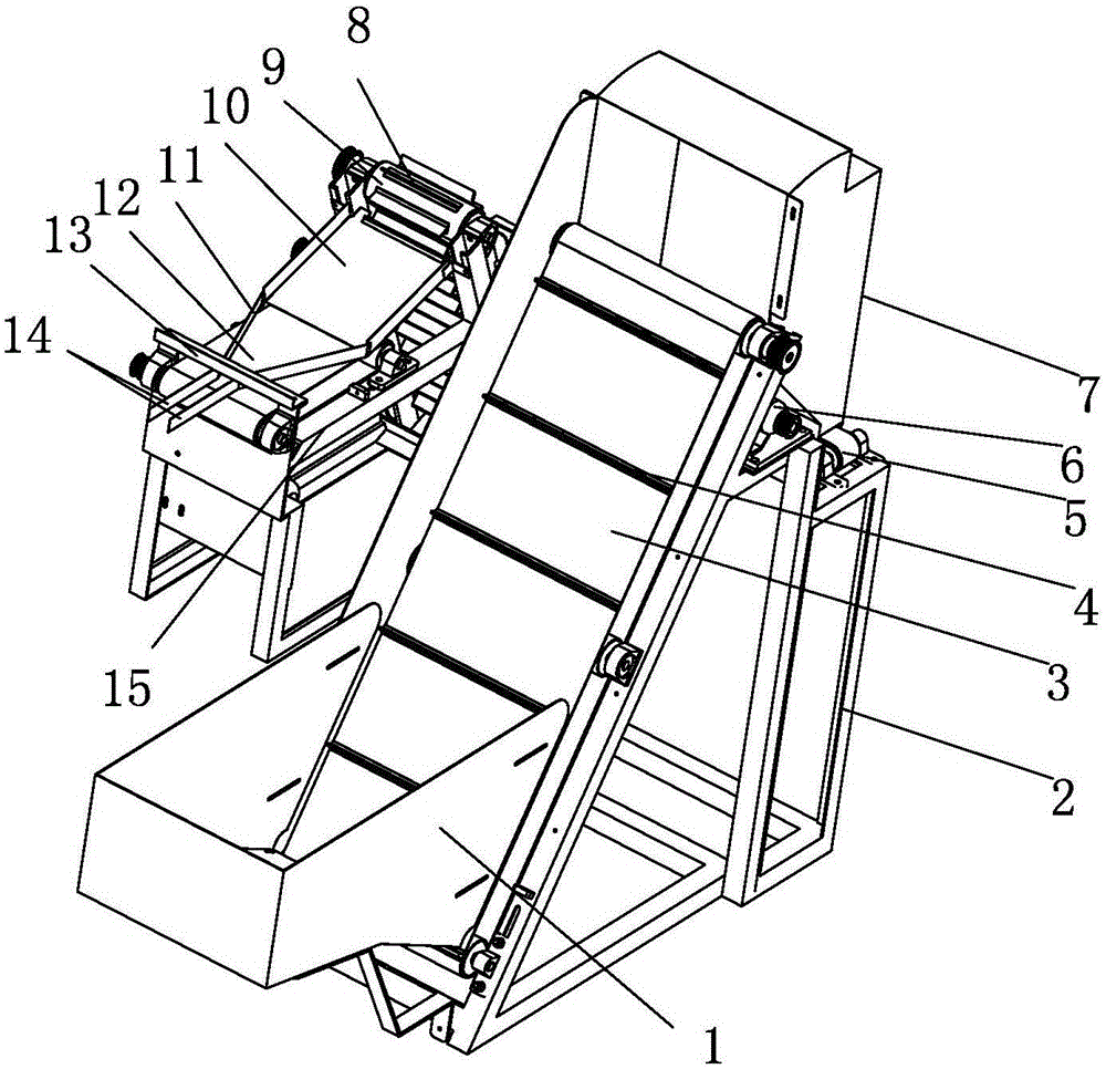
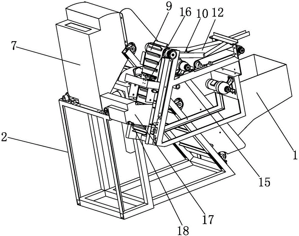
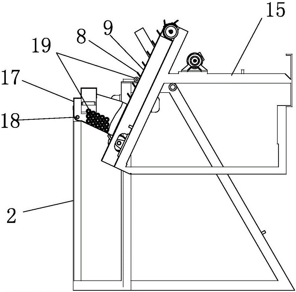
[0020] Such as Figure 1~Figure 3As shown, the present invention includes bobbin silo, first lifting mechanism, yarn management direct conveying mechanism, second lifting mechanism, large bobbin rejecting mechanism and orientation mechanism, and bobbin silo is fixedly installed by a frame, and the The first lifting mechanism includes a first lifting channel and a first lifting drive mechanism that drives the first lifting channel to move upward. The first lifting channel is installed obliquely on the frame, and the lower end of the first lifting channel extends into the bobbin silo, the upper rear side of the first lifting channel is used as the outlet end, the bottom of the first lifting channel is provided with horizontally distributed bobbin pallets at intervals, and the bottom of the first lifting channel is The first lifting conveyor bel...


PUM


Abstract

The invention belongs to the technical field of textile machines, and discloses a directional bobbin conveying device of a bobbin arranging machine. The directional bobbin conveying device comprises a bobbin bin, a first-stage lifting mechanism, a bobbin straightening conveying mechanism, a second-stage lifting mechanism, a large bobbin removing mechanism and a directional mechanism. Bobbins are lifted in two stages through the first-stage lifting mechanism and the second-stage lifting mechanism, so that the bobbin lifting speed is greatly increased; besides, the bobbins are directionally conveyed at a constant speed, so that the bobbin arranging efficiency is improved. Large bobbins with end yarns wound are accurately removed in the lifting process, and a beating mechanism is adopted in the large bobbin removing process, so that compared with an air cylinder structure, the handling speed is greatly increased, and the structure is simple. The physical principle that the rolling speed of the large ends of the bobbins is larger than that of the small ends of the bobbins in the directional bobbin conveying process is utilized, and an optimized angle is adopted to make the bobbins roll at the maximum angle without sliding relative to a directional roller path, so that the bobbins are rapidly pulled to a next process when the large ends of the bobbins roll onto conveying belts, and the function of rapidly and directionally arranging bobbins is achieved.

Description

technical field [0001] The invention belongs to the technical field of textile machinery, and in particular relates to a bobbin directional conveying device of a bobbin management machine. Background technique [0002] For the automatic winding machine used by textile enterprises, the yarn bobbins that come out are all messy and fall in the storage area. The bobbins used on the spinning frame are tapered tubes with one end large and the other end small, and there are often many colors. When these When the bobbin is used again, it needs to be sorted and collected according to the different colors for the next use. It is also necessary to remove the large bobbins with excess yarn. At present, some small textile enterprises usually rely on manual sorting and straightening out, which is inefficient. The labor intensity is high and the production cost is high, and some large enterprises use management equipment, but the management equipment on the existing market has a slow manag...

Claims


Application Information

Patent Timeline
Patent Type & Authority Applications(China)
IPC IPC(8): B65G47/14
CPCB65G47/1407B65G2201/0232
Inventor 顾利江竺海华潘旭东
Owner ZHEJIANG ZILI MACHINERY
Why Eureka
Try Eureka