

Waste garbage gear type rapid shredding device for 3D printing
A technology of 3D printing and shredding device
- Summary
- Abstract
- Description
- Claims
- Application Information
AI Technical Summary
Problems solved by technology
Method used
Image

Examples
Embodiment 1
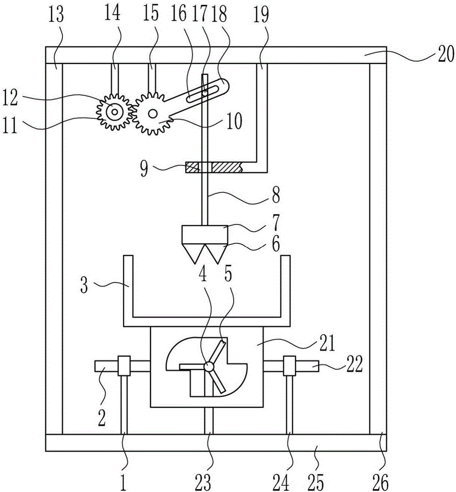
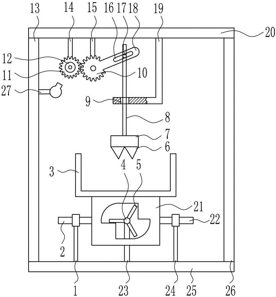
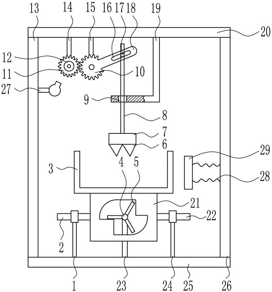
[0034] A 3D printing waste garbage gear type fast shredding device, such as Figure 1-4As shown, it includes a first guide sleeve 1, a first guide rod 2, a shredding frame 3, a first motor 4, a rotating rod 5, a cutter 6, a fixed block 7, a lifting rod 8, a first gear 10, a second Gear 11, second motor 12, left frame 13, first bracket 14, second bracket 15, sliding shaft 17, swing lever 18, guide plate 19, top plate 20, moving frame 21, second guide rod 22, connecting rod 23 , the second guide sleeve 24, the base plate 25 and the right frame 26, the base plate 25 top is provided with the left frame 13, the first guide sleeve 1, the connecting rod 23, the second guide sleeve 24 and the right frame 26 successively from left to right, the first A first guide rod 2 is provided in the guide sleeve 1, a second guide rod 22 is provided in the second guide sleeve 24, a moving frame 21 is arranged between the first guide rod 2 and the second guide rod 22, and a moving frame 21 is arran...
PUM
| Property | Measurement | Unit |
|---|---|---|
| Diameter | aaaaa | aaaaa |
| Length | aaaaa | aaaaa |
| Height | aaaaa | aaaaa |
Abstract
Description
Claims
Application Information