Intelligent vibration reduction boring bar and vibration reduction control method

A technology of intelligent vibration reduction and intelligent controller, applied in boring bars and other directions, can solve the problems of lack of automatic vibration reduction adjustment function, difficult maintenance and repair, and large active vibration reduction boring bar system, so as to solve the problem of automatic vibration reduction. Adjustment function, easy maintenance and repair, simple structure effect

Active Publication Date: 2017-01-04
HARBIN UNIV OF SCI & TECH
View PDF11 Cites 21 Cited by
  • Summary
  • Abstract
  • Description
  • Claims
  • Application Information

AI Technical Summary

Problems solved by technology

[0009] The present invention proposes an intelligent vibration-damping boring bar and its vibration-damping control method in order to solve the problems that the existing passive vibrati

Method used


Image

  • Intelligent vibration reduction boring bar and vibration reduction control method
  • Intelligent vibration reduction boring bar and vibration reduction control method
  • Intelligent vibration reduction boring bar and vibration reduction control method

Examples


Embodiment 1

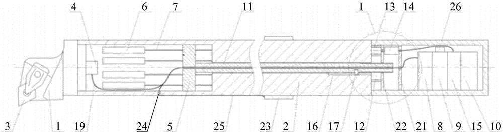
[0041] Embodiment one: combine below figure 1 This embodiment will be described in detail. An intelligent damping boring bar described in this embodiment includes a cutter head 1, a cutter bar 2 and an intelligent controller;

[0042] The cutter head 1 is fixedly arranged on the front end of the cutter bar 2 for clamping the blade 3;

[0043] Inside the cutter bar 2, a cavity is provided near the front end thereof;

[0044] A triaxial acceleration sensor 4, multiple groups of cantilever vibration-absorbing units and a sliding seat 5 are arranged inside the cavity;

[0045] The triaxial acceleration sensor 4 is fixedly arranged on the front end face of the cavity;

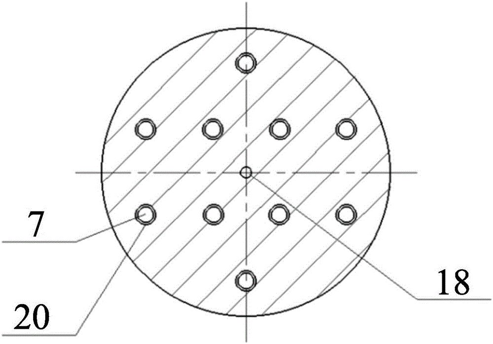
[0046] Each group of cantilever vibration-absorbing units includes a mass block 6 and a cantilever beam 7, one end of the cantilever beam 7 is fixedly connected to the mass block 6, and the other end of the cantilever beam 7 is fixedly arranged on the rear end surface of the cavity. 7 runs through the sliding se...

Embodiment 2

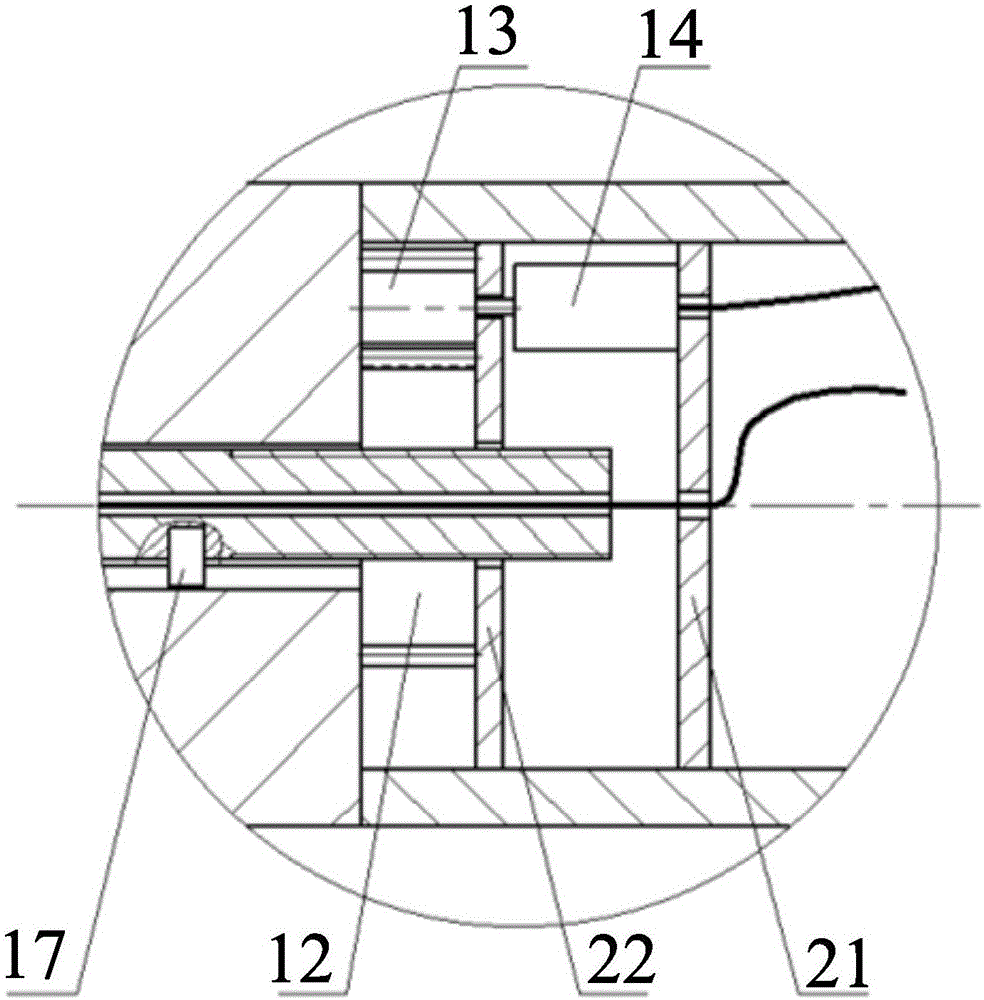
[0054] Embodiment two: combine below figure 1 and figure 2 This embodiment will be described in detail. This embodiment further defines the smart damping boring bar described in the first embodiment. An intelligent damping boring bar described in this embodiment, the transmission unit includes a push rod 11, a first gear 12, a second gear 13, a motor 14 and a driver 15;

[0055] The power supply unit 10 is also used to provide the motor 14 and the driver 15 with the electric energy required for work;

[0056] The data processing unit 9 is used to control the running and stopping of the driver 15;

[0057] The driver 15 is used to drive the motor 14;

[0058] The shaft of the motor 14 is coaxially fixed with the second gear 13;

[0059] The first gear 12 meshes with the second gear 13;

[0060] The first gear 12 is arranged coaxially with the push rod 11, one end of the push rod 11 is threadedly connected with the first gear 12, and the other end of the push rod 11 is fixe...

Embodiment 3

[0062] Embodiment three: the following combination figure 1 This embodiment will be described in detail. This embodiment further defines the smart damping boring bar described in the second embodiment. An intelligent damping boring bar described in this embodiment is also provided with a first through hole inside the tool bar 2, the first through hole communicates with the cavity and the inner space of the housing, and the first through hole communicates with the inner space of the housing. The inner diameter of the through hole is equal to the diameter of the push rod 11, and the push rod 11 located in the first through hole is arranged coaxially with the sliding seat 5;

[0063] In the first through hole, a sliding groove 16 is arranged at a position close to the rear end of the cutter bar 2, and the length direction of the sliding groove 16 is parallel to the axis of the first through hole;

[0064] On the push rod 11, a slide pin 17 is arranged near one end thereof;

[...


PUM


Abstract

The invention provides an intelligent vibration reduction boring bar and a vibration reduction control method and belongs to the field of machining. The problems that an existing passive vibration reduction boring bar has no automatic vibration reduction adjusting function, and an active vibration reduction boring bar system is large and difficult to maintain and repair are solve. According to the boring bar, a three-axis accelerator sensor, multiple cantilever vibration absorption units and a sliding base are arranged in a cavity at the front end of a cutter bar. Each cantilever vibration absorption unit comprises a mass block and a cantilever beam, wherein the two ends of the cantilever beam are fixed to the mass block and the rear end face of the cavity respectively. A data processing unit calculates acceleration data of the pointed end of a blade according to acceleration data measured by the sensor, the sliding base is controlled by a transmission unit to slide in the cavity, and accordingly the overhanging amount of the cantilever beams is changed. The method includes the steps that the data processing unit controls the sliding base to slide from one end of each cantilever beam to the other end, in the process, the data processing unit determines the slider optimal position corresponding to the minimum acceleration data at the pointed end of the blade, and a slider is controlled to slide to the position. The boring bar is used for deep hole boring.

Description

technical field [0001] The invention relates to the field of machining, in particular to an intelligent damping boring bar and a damping control method thereof. Background technique [0002] Deep hole boring has always been a difficult point in the field of machining. The difficulty lies in the fact that the boring bar needs to go deep into the interior of the workpiece during the deep hole boring process. The longer the hole depth of the workpiece, the longer the overhang length of the boring bar, and the stiffness of the boring bar decreases with the increase of the overhang length, which leads to deformation of the boring bar with accompanying vibration behavior. The vibration of the boring bar will affect the machining accuracy of the deep hole and the smoothness of the inner wall. In severe cases, the workpiece will be unqualified or even scrapped. [0003] The vibration reduction methods of existing boring bars mainly include the following categories: [0004] 1. Red...

Claims


Application Information

Patent Timeline
IPC IPC(8): B23B29/02
CPCB23B29/022
Inventor 刘献礼刘强吴石马晶
Owner HARBIN UNIV OF SCI & TECH
Why Eureka
Try Eureka