Method for laser welding of vibration motor clip and mass block

A vibration motor, laser welding technology, applied in laser welding equipment, welding equipment, metal processing equipment and other directions, can solve the problems of insufficient strength, high melting point, difficult to meet welding strength and appearance requirements, etc., to ensure repeated positioning accuracy and appearance. smooth and flat effect

Active Publication Date: 2017-01-04
WUHAN HGLASER ENG CO LTD
View PDF4 Cites 8 Cited by
  • Summary
  • Abstract
  • Description
  • Claims
  • Application Information

AI Technical Summary

Problems solved by technology

The general laser welding process is difficult to meet the requirements of welding strength and appearance. Due to the high melting point of tungsten-nickel alloy steel, positive defocus welding (laser focus is above the surface of the workpiece) is used, and the penetration depth of the solder joint is low and the strength is not enough.

Method used


Image

  • Method for laser welding of vibration motor clip and mass block
  • Method for laser welding of vibration motor clip and mass block
  • Method for laser welding of vibration motor clip and mass block

Examples


Embodiment Construction

[0019] pass below Figure 1 ~ Figure 3 And the way of enumerating some optional embodiments of the present invention, the technical solution of the present invention (including the preferred technical solution) is described in further detail, and any technical feature and any technical solution in this embodiment do not limit the protection scope of the present invention .

[0020] The laser welding method of the vibrating motor shrapnel and mass block designed by the present invention comprises the following steps:

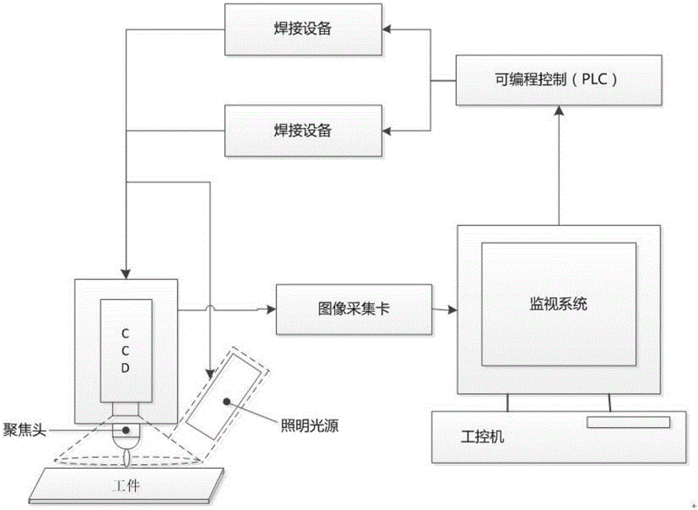
[0021] 1. Use CCD vision to accurately locate the welding position: Use CCD vision camera to identify and take pictures of the feature points of the product, compare the position of the solder joints on the product with the feature points, and form the coordinate values ​​​​of the required solder joints on the corresponding software , relying on the laser motion control mechanism (such as scanning galvanometer) to transmit the laser to the required welding spot ...


PUM

PropertyMeasurementUnit
thicknessaaaaaaaaaa
melting pointaaaaaaaaaa

Abstract

The invention discloses a method for laser welding of a vibration motor clip and a mass block. The method comprises the steps of 1, conducting precise positioning on a welding position by means of CCD vision; 2, setting an M-shaped welding waveform, wherein energy is increased slowly and lasts for a while, then energy is reduced and increased again and lasts for a while, and finally energy is reduced to zero; 3, finding out the focal position of a focus lens and the distance between the focus lens and a workpiece; 4, adjusting the focal point of the focus lens to a position below the surface of the workpiece, and conducting step-by-step adjustment of the focal position of laser light multiple times to enable the focal point to move downwards and get away from the surface of the workpiece till spatter does not occur during welding and welding strength meets the requirement. By the adoption of CCD vision positioning, the position accuracy of a welding spot reaches 0.03mm, and repeated positioning precision of the welding spot during production is guaranteed; by the adoption of the M-shaped waveform and the negative defocus welding method, the strength of a single welding spot can reach 3 kg, and the welding spot is smooth and flat.

Description

technical field [0001] The invention belongs to the technical field of laser welding, and in particular relates to a laser welding process method for a shrapnel and a quality block of a vibration motor. Background technique [0002] Vibration motors are widely used in mobile phones, tablet computers or environments that require vibration to achieve vibration functions, instead of sound prompts, so as to avoid disturbing others or generating noise. The mass blocks, shrapnel and stoppers in the vibration motor need to be overlapped together and require high strength. Ordinary welding methods are difficult to meet the strength requirements, so laser welding must be used, and a large number of general laser welding uses Nd:YAG lasers, and Nd:YAG lasers consume a lot of power, occupy a large area, and have poor energy stability. Meet the precision welding requirements of vibration motors. [0003] As the volume design of the vibration motor becomes smaller and smaller, the weld...

Claims


Application Information

Patent Timeline
Patent Type & Authority Applications(China)
IPC IPC(8): B23K26/22B23K26/03B23K26/046B23K26/0622
CPCB23K26/032B23K26/046B23K26/0622B23K26/22
Inventor 王建刚刘勇向发午杨威
Owner WUHAN HGLASER ENG CO LTD
Why Eureka
Try Eureka