High-hydrostatic grinding equipment and grinding method
A hydrostatic and grinding technology, which is applied in the direction of grinding/polishing equipment, grinding drive devices, metal processing equipment, etc., can solve the problem of low grinding consumption, low surface and subsurface crack damage, difficult high material removal rate and other problems to achieve the effect of suppressing processing damage and increasing the critical load value
- Summary
- Abstract
- Description
- Claims
- Application Information
AI Technical Summary
Problems solved by technology
Method used
Image

Examples
Embodiment 1
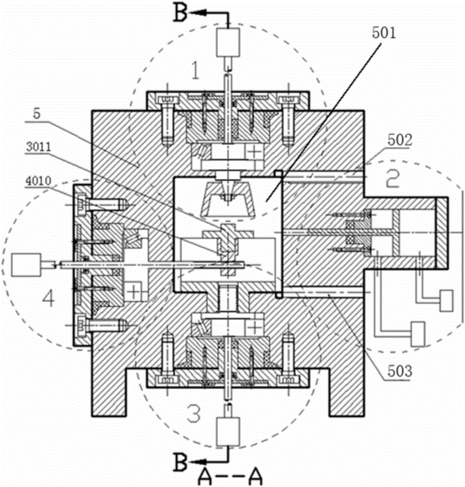
[0096] Such as figure 1 , a high hydrostatic grinding equipment, the equipment includes a grinding wheel frame system 1, a booster system 2, a vertical feed system 3, a horizontal feed system 4 and a box 5. A cavity 501 is provided inside the box body 5 . The wheelhead system 1 is located on the upper part of the box body 5 and extends into the cavity 501 . The vertical feeding system 3 is located at the lower part of the box body 5 and extends into the cavity 501 . The pressurization system 2 is located on the left side of the box body 5 and extends into the cavity 501 . The horizontal feed system 3 is located on the right side of the box body 5 and extends into the cavity 501 . The box body 5 is also provided with an oil inlet hole 502 and an oil outlet hole 503 .
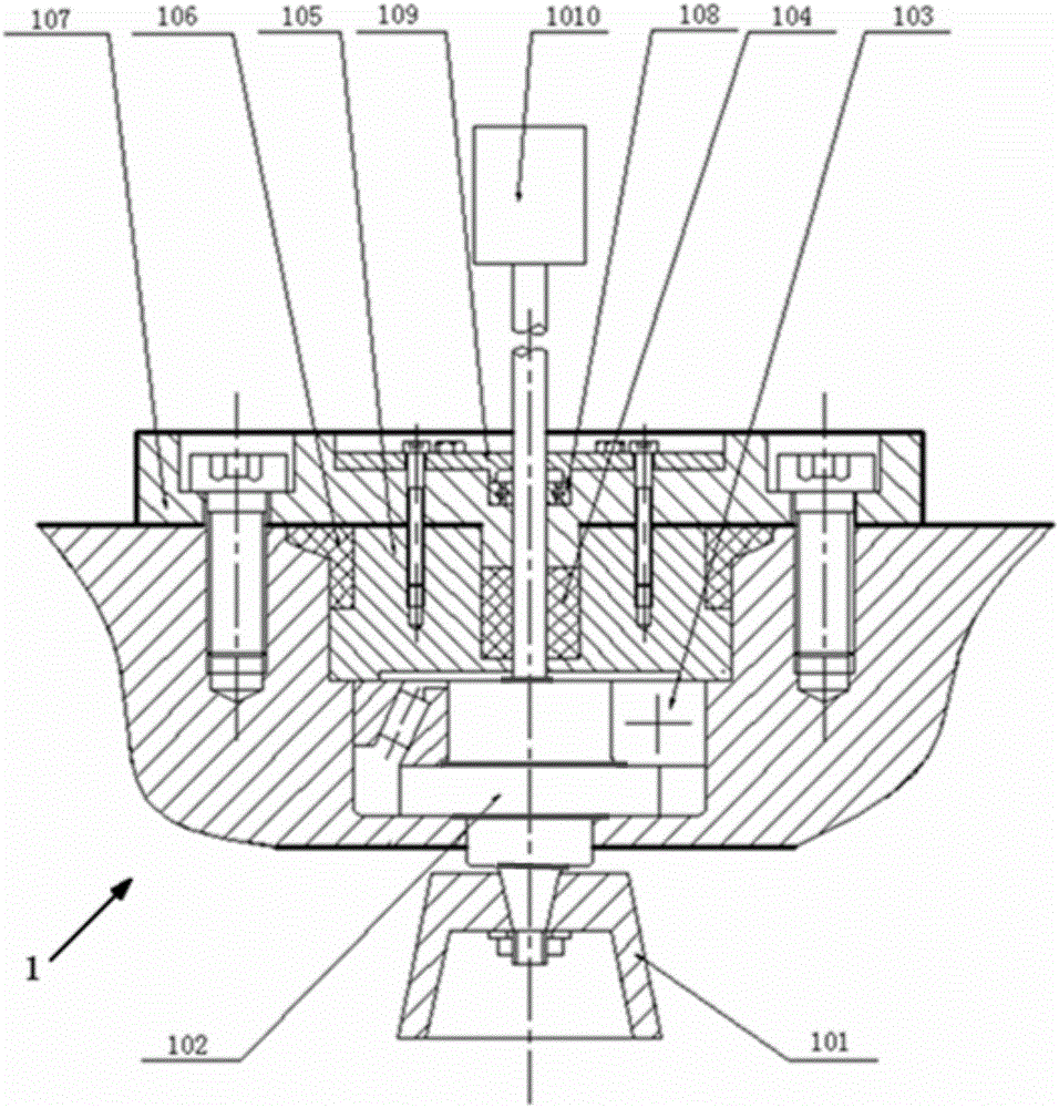
[0097] Such as figure 2 , the grinding wheel head system 1 includes a grinding wheel 101, a grinding wheel spindle 102, a grinding wheel tapered roller bearing 103, a grinding wheel bearing block 105, a gri...
Embodiment 2
[0101] Repeating Example 1, the device also includes a monitoring system 6 . Such as Figure 7 , the monitoring system 6 is set on the box 5,. The monitoring system 6 includes a pressure sensor 601 , a temperature sensor 602 , a force sensor 603 , a displacement sensor 604 and a monitoring box cover 7 . The monitoring box cover 7 is provided with a pressure hole 701, a temperature hole 702, and a center hole 703 for force and displacement. Wherein the pressure sensor 601 is contained on the pressure hole 701 on the monitoring box cover 7 . The temperature sensor 602 is installed on the temperature hole 702 on the monitoring box cover 7 . The force sensor 603 and the displacement sensor 604 are installed on the workbench 3011 . The force sensor 603 and the displacement sensor 604 are connected to the monitoring system 6 through the force and displacement central hole 703 . A first monitoring sealing ring 704 is installed between the force and displacement center hole 703 a...
Embodiment 3
[0103] Repeat Example 1, except that the boosting multiple of the boosting system 2 is 15 times, and the high hydrostatic pressure generated in the box body 5 is 500 MPa.
PUM
 Abstract
Description
Claims
Application Information
 - R&D
- Intellectual Property
- Life Sciences
- Materials
- Tech Scout
- Unparalleled Data Quality
- Higher Quality Content
- 60% Fewer Hallucinations
Browse by: Latest US Patents, China's latest patents, Technical Efficacy Thesaurus, Application Domain, Technology Topic, Popular Technical Reports.
© 2025 PatSnap. All rights reserved.Legal|Privacy policy|Modern Slavery Act Transparency Statement|Sitemap|About US| Contact US: help@patsnap.com