Extruder with hollow screw

A hollow screw and extruder technology, applied in the field of polymer material molding equipment, can solve problems such as affecting the service life and energy consumption of the machine, increasing manufacturing and use costs, affecting the quality of processed products, etc., to eliminate insufficient rigidity and poor stability. , Improve physical properties, reduce the effect of scratching and friction

Inactive Publication Date: 2017-01-04
SHUNDE POLYTECHNIC
View PDF4 Cites 0 Cited by
  • Summary
  • Abstract
  • Description
  • Claims
  • Application Information

AI Technical Summary

Problems solved by technology

[0002] Plastic extrusion molding machine is an important equipment for processing polymers. After polymers (granules, powders, etc.) enter the barrel and screw groove space through the hopper, they move forward under the push of the screw flight. Every time the screw rotates, The material moves forward by a lead, and the material has to go through a series of processes such as plasticizing and melting in the screw groove. Its shape changes from the initial solid state to the molten state through many links such as plug flow, molten film, circulation and solid phase crushing. state, and then molded into plastic products through machine heads, molds and other equipment. Obviously, in plastic extrusion molding machines, the screw is the most important and core component. Its structure and shape not only affect the quality of processed products, but also affect the machine. Service life and energy consumption
If the traditional single-screw extruder is used to ensure the completion of this series of links, the screw structure will inevitably be complicated, the length will increase, and it will also bring a series of problems associated with long screws, such as: insufficient rigidity, poor stability and screw to machine. Severe scraping and friction of the barrel; other extrusion equipment that uses multi-screw processing, although multi-screw extruder has many advantages, it also brings problems such as complex structure, increased manufacturing and use costs, etc.
[0003] There are also some plastic machines that use a hollow screw. After consulting the relevant patent documents, I found the two patents listed below, and found that although they all adopted the "hollow" screw scheme similar to the present invention, their inner cavities have no screw. The grooves are all smooth cylindrical or conical surfaces, and the mechanism of action is also far from that of the present invention. There are two main differences: one is that the screw rods in these patents only have screw grooves on the outer surface, and the inner shape The cavity has no screw groove; the second is that in these patents, the axial movement of the material flow in the screw groove is in a single direction: that is, from the hopper into the groove, and then move along the axis of the screw toward the extruder head
[0004] Example 1, the patent "Coaxial Multi-screw Extruder" (publication number CN1059151C) discloses an extruder with multi-screw and multi-sleeve. The extruder described in this patent has two screws, two sleeve, but its two screw rods only have screw grooves on its outer circular surface, and its inner profile has no screw grooves, while its two sleeves have no screw grooves on its inner and outer circular surfaces. Said extruder is equipped with coaxial multi-layer material cylinder and screw rod, can extrude the material of the multi-layer different composition of wrapping simultaneously, and the technology described in the present invention is quite different, and its structure is complicated

Method used


Image

  • Extruder with hollow screw
  • Extruder with hollow screw
  • Extruder with hollow screw

Examples


Embodiment Construction

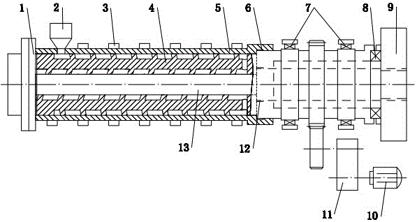
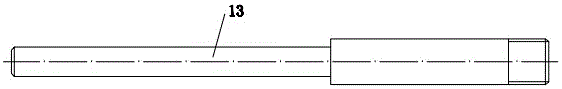
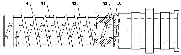
[0025] The specific embodiments of the present invention will be further described below in conjunction with the accompanying drawings. It should be noted here that the descriptions of these embodiments are used to help understand the present invention, but are not intended to limit the present invention. In addition, the technical features involved in the various embodiments of the present invention described below may be combined with each other as long as they do not constitute a conflict with each other.

[0026] In the description of the present invention, the orientations or positional relationships indicated by the terms "left" and "right" are based on the orientations or positional relationships shown in the drawings, which are only for the convenience of describing the present invention and do not require that the present invention must be based on a specific orientation. construction and operation, therefore, should not be construed as limiting the invention.

[002...


PUM


Abstract

The invention relates to an extruder with a hollow screw. The extruder comprises an extruder head, a hopper, an electric heating ring, the hollow screw, an extruder barrel, a first heat resisting sealing ring, a second heat resisting sealing ring, radial bearings, a thrust bearing, a seat, a motor, a transmission mechanism and a mandrel with a heater. The extruder head is located at the left end of the hollow screw which is sleeved with the extruder barrel, the mandrel is arranged in the hollow screw, and the hopper is mounted at the left end of the extruder barrel; and the extruder barrel is sleeved with the electric heating ring, the first heat resisting sealing ring is arranged between the hollow screw and the right end of the extruder barrel, and the second heat resisting sealing ring is arranged between the hollow screw and the mandrel. The extruder is characterized in that spiral grooves are formed in the outer molded surface and an inner mold cavity of the hollow screw correspondingly, a through hole enabling the external spiral groove and the internal spiral groove to communicate is formed in the right end of the portion, located at the right end of the spiral grooves, of the hollow screw, and the external spiral groove and the internal spiral groove are opposite in spiral direction; and a discharge outlet of the hopper communicates with the external spiral groove. The extruder has the advantages that the structure is simple, the length of the hollow screw can be greatly reduced, the service life of the extruder can be prolonged, the productivity of the extruder is remarkably improved, and thermal efficiency is improved.

Description

technical field [0001] The invention relates to an extruder with a hollow screw, which is mainly used for mixing, plasticizing and extruding polymer materials, and belongs to the technical field of polymer material molding equipment. Background technique [0002] Plastic extrusion molding machine is an important equipment for processing polymers. After polymers (granules, powders, etc.) enter the barrel and screw groove space through the hopper, they move forward under the push of the screw flight. Every time the screw rotates, The material moves forward by a lead, and the material has to go through a series of processes such as plasticizing and melting in the screw groove. Its shape changes from the initial solid state to the molten state through many links such as plug flow, molten film, circulation and solid phase crushing. state, and then molded into plastic products through machine heads, molds and other equipment. Obviously, in plastic extrusion molding machines, the s...

Claims


Application Information

Patent Timeline
Patent Type & Authority Applications(China)
IPC IPC(8): B29C47/38B29C47/60B29C47/66B29C48/395
CPCB29C48/397B29C48/51B29C48/681B29C48/685
Inventor 陈学锋凃明霞徐言生胡建国
Owner SHUNDE POLYTECHNIC
Why Eureka
Try Eureka