
Groove-shaped wall structure of ship oil cabin

A wall structure and groove type technology, applied in the direction of hull bulkhead, hull, ship construction, etc., can solve the difficulty of increasing the installation process of the vertical groove wall, increase the thickness of the vertical groove wall steel plate, and increase the vertical groove shape Problems such as wall weight can be avoided to achieve the effect of avoiding centering, reducing weight and reducing welding

Active Publication Date: 2017-01-04
GUANGZHOU SHIPYARD INTERNATIONAL LTD
View PDF6 Cites 7 Cited by
  • Summary
  • Abstract
  • Description
  • Claims
  • Application Information

AI Technical Summary

Problems solved by technology

Since the vertical trough wall is very long from top to bottom, the span is large. In order to enhance its strength, the upper wall pier and the lower wall pier are reinforced to enhance the strength of the vertical trough wall. However, the upper wall pier and the lower pier The structure of the wall pier is very complicated. When connecting the vertical groove wall with the upper and lower wall piers, it is usually necessary to align the vertical groove wall with the corresponding wall piers, which increases the difficulty of the installation process of the vertical groove wall and makes it The installation efficiency is low, and due to the complex structure of the upper and lower wall piers, it is unfavorable for welding, grinding, painting and other operations during the installation process; due to the long span of the vertical groove wall, in order to further ensure the vertical groove wall For bearing strength, it is necessary to increase the thickness of the steel plate for making the vertical groove wall, so the weight of the vertical groove wall is greatly increased; in addition, due to the existence of upper and lower wall piers, the tank capacity space of the oil tank is also reduced

Method used


Image

  • Groove-shaped wall structure of ship oil cabin
  • Groove-shaped wall structure of ship oil cabin
  • Groove-shaped wall structure of ship oil cabin

Examples


Embodiment Construction

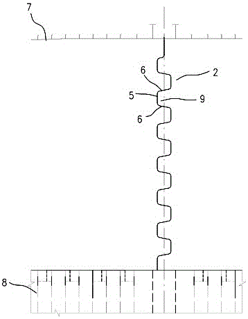
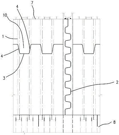
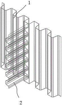
[0009] A channeled wall structure for a ship's cabin, such as Figure 1 to Figure 3 As shown, it includes the front wall of the cabin and the longitudinal oil-tight wall of the cabin perpendicular to the front wall of the cabin. The front wall of the cabin is a vertical grooved wall 1, and the longitudinal oil-tight wall of the cabin is a horizontal grooved wall 2. The trough wall 1 includes a plurality of vertical panels 3 perpendicular to the bottom surface of the cabin, and the adjacent vertical panels 3 are arranged in a front-to-rear staggered position, and the adjacent vertical panels 3 are connected by the first connecting web 4 to form a vertical panel with a wave structure. The grooved wall 1; the horizontal grooved wall 2 includes a plurality of horizontal panels 5 arranged from top to bottom vertically on the bottom surface of the cabin, and the adjacent horizontal panels 5 are arranged in a left and right misalignment, and the adjacent horizontal panels 5 pass throu...


PUM


Abstract

A groove-shaped wall structure of a ship cabin comprises a cabin front wall and a cabin longitudinal oil tight wall which is perpendicular to the cabin front wall, wherein the cabin front wall is a perpendicular groove-shaped wall; the cabin longitudinal oil tight wall is a horizontal groove-shaped wall; the perpendicular groove-shaped wall comprises a plurality of vertical panels which are perpendicular to the bottom surface of the cabin; the adjacent vertical panels are arranged in a front and back staggered mode and are integrally connected by first connecting web plates to form the perpendicular groove-shaped wall with a wave structure; the horizontal groove-shaped wall comprises a plurality of horizontal panels which are perpendicular to the bottom surface of the cabin and are arranged from top to bottom; the adjacent horizontal panels are arranged in a left and right staggered mode and are integrally connected by second connecting web plates to form the horizontal groove-shaped wall with a wave structure; the side of the horizontal groove-shaped wall is fixedly connected with the vertical panel, at the corresponding end, of the perpendicular groove-shaped wall; the upper side and the lower side of the horizontal groove-shaped wall are fixedly connected with an upper deck and the bottom surface of the cabin correspondingly. The groove-shaped wall structure has the advantages of simple structure, high bearing strength, light weight and high cabin capacity.

Description

technical field [0001] The invention relates to a grooved wall structure for a ship's oil tank. Background technique [0002] The bulkhead of the existing ship oil tank adopts a vertical groove wall, the upper end and the lower end of the vertical groove wall are respectively connected with the upper wall piers and the lower wall piers, the upper wall piers are connected with the upper deck, and the lower wall piers are connected with the upper deck. Oil tank bottom connection. Since the vertical trough wall is very long from top to bottom, the span is large. In order to enhance its strength, the upper wall pier and the lower wall pier are reinforced to enhance the strength of the vertical trough wall. However, the upper wall pier and the lower pier The structure of the wall pier is very complicated. When connecting the vertical groove wall with the upper and lower wall piers, it is usually necessary to align the vertical groove wall with the corresponding wall piers, which...

Claims


Application Information

Patent Timeline
IPC IPC(8): B63B3/60
CPCB63B3/60
Inventor 茆海
Owner GUANGZHOU SHIPYARD INTERNATIONAL LTD
Learn More