Improved jet aerator

An improved technology of jet aeration, applied in water aeration, chemical instruments and methods, sustainable biological treatment, etc., can solve the problem of small contact area between air bubbles and sewage, unable to meet the requirements of aeration treatment, and the mixing of air and water is not special Sufficient and other issues to achieve the effect of improving the oxygen melting effect, improving the transfer efficiency, and improving the aeration effect

Inactive Publication Date: 2017-01-04
宜兴市中发水处理环保设备有限公司
View PDF6 Cites 4 Cited by
  • Summary
  • Abstract
  • Description
  • Claims
  • Application Information

AI Technical Summary

Problems solved by technology

The jet aerator is neither a bubble diffusion device nor a mechanical aeration equipment, but an aeration equipment between the two. It uses the two functions of bubble diffusion and hydraulic shear to achieve aeration. The purpose of gas and mixing, but the gas-water mixing of the existing jet aerator is not particularly sufficient, resulting in relatively low oxygenation efficiency, and in addition, the contact area between gas-water mixed bubbles and sewage is relatively small, resulting in oxygen transfer efficiency Low, the overall aeration effect is not ideal, and cannot meet some high-standard aeration treatment requirements

Method used


Image

  • Improved jet aerator
  • Improved jet aerator
  • Improved jet aerator

Examples


Embodiment 1

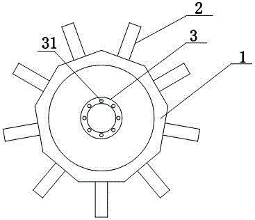
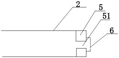
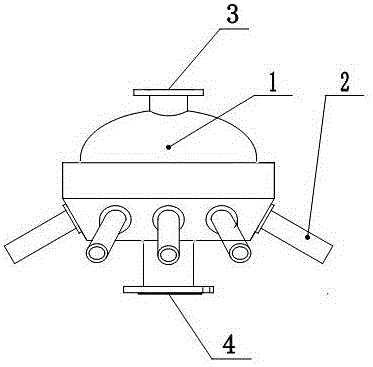
[0015] Such as figure 1 , figure 2 and image 3 As shown, the present invention provides an improved jet aerator, which includes a casing 1 and jet aeration heads 2 evenly arranged on the surface of the casing 1. The top and bottom ends of the casing 1 are respectively provided with air inlet Inlet 3 and water inlet 4, a flow control block 5 is arranged at the water outlet end in the jet aerator head 2, and a converging flow outlet hole 51 is arranged on the flow control block 5, and the water outlet of the converging flow outlet hole 51 The end is provided with a stainless steel mesh 6, and the stainless steel mesh 6 is covered outside the water outlet end of the water gathering outlet 51, and the water gathering outlet 51 is located at the center of the flow control block 5, and the flow control block 5 is connected with the jet aeration The head 2 is integrally formed, and the air inlet 3 and the water inlet 4 are fixed on the housing 1 by several fixing bolts 31 .

Embodiment 2

[0017] Such as figure 1 , figure 2 and image 3 As shown, the sewage enters the housing 1 from the water inlet 4, and the air enters the housing 1 from the air inlet 3. The air and sewage in the housing 1 are fully mixed and fused to form air-water mixed bubbles, and the air-water mixture The air bubbles enter the jet aerator head 2 and are sprayed out through the outlet hole 51 of the flow control block 5. The sprayed air-water mixed air bubbles are divided into smaller air bubbles by the stainless steel mesh 6, and the air bubbles enter the sewage Fully contact with sewage to achieve aeration effect.


PUM


Abstract

The invention discloses an improved jet aerator. The improved jet aerator comprises a casing and jet aeration heads arranged on the surface of the casing uniformly, wherein an air inlet and a water inlet are formed in the top end and the bottom end of the casing respectively, a flow control block is arranged at a water outlet end in each jet aeration head, a gathering water outlet hole is formed in each flow control block, and a stainless steel wire is arranged at a water outlet end of each gathering water outlet hole and covers the water outlet end of the gathering water outlet hole. The improved jet aerator is simple in structure and reasonable in design, air and water mixed bubbles in the jet aeration heads are sprayed out of the gathering water outlet holes with smaller areas in a stronger, more powerful and rapid manner, the oxygen dissolving effect of the air and water mixed bubbles in sewage is improved, the sprayed air and water mixed bubbles are divided into smaller bubbles by the stainless steel wire, the contact area of the bubbles and the sewage is increased, the oxygen transferring efficiency is improved, and the overall aeration effect is substantially improved.

Description

technical field [0001] The invention relates to the field of water treatment, in particular to an improved jet aerator. Background technique [0002] Jet aeration is an aeration method currently used in sewage biochemical treatment. The jet aerator is neither a bubble diffusion device nor a mechanical aeration equipment, but an aeration equipment between the two. It uses the two functions of bubble diffusion and hydraulic shear to achieve aeration. The purpose of gas and mixing, but the gas-water mixing of the existing jet aerator is not particularly sufficient, resulting in relatively low oxygenation efficiency, and in addition, the contact area between gas-water mixed bubbles and sewage is relatively small, resulting in oxygen transfer efficiency Low, the overall aeration effect is not very ideal, and cannot meet some high-standard aeration treatment requirements. Contents of the invention [0003] Purpose of the invention: In order to overcome the deficiencies in the ...

Claims


Application Information

Patent Timeline
Patent Type & Authority Applications(China)
IPC IPC(8): C02F3/02C02F7/00
CPCC02F3/02C02F7/00Y02W10/10
Inventor 陈立中叶超刘超裴红卫孙红卫陈皓张先妹李洁
Owner 宜兴市中发水处理环保设备有限公司
Why Eureka
Try Eureka