

A geothermal well heat circulation method
A geothermal well and geothermal technology, applied in the directions of geothermal energy, geothermal energy power generation, geothermal collectors, etc., can solve the problem that the injected hydrothermal energy cannot meet the actual needs, achieve a good market prospect, expand the involved fields and workload, and reduce costs Effect
- Summary
- Abstract
- Description
- Claims
- Application Information
AI Technical Summary
Problems solved by technology
Method used
Image

Examples
Embodiment 1
[0041] In order to overcome the impractical problem of taking out heat energy in the existing method, the present invention provides such as figure 1 A geothermal well thermal cycle system is shown, the invention is used to ensure the high-efficiency thermal cycle under the conventional displacement of the thermal cycle of the existing geothermal well, further improves the underground heat exchange efficiency, and effectively prolongs the production life of the geothermal well . It solves the technical problem of low efficiency of using underground heat energy by geothermal wells, expands the fields and workload involved in the use of underground heat energy by geothermal wells, and effectively reduces the cost of using underground heat energy by geothermal wells.
[0042] The technical scheme adopted in the present invention is:
[0043] A geothermal well heat circulation system, the specific steps are:
[0044] Step 1 Select a well location in the geothermal accumulation a...
Embodiment 2
[0060] Based on the above-mentioned embodiment, in this embodiment, in the step 12, the specific steps of the cycle are:
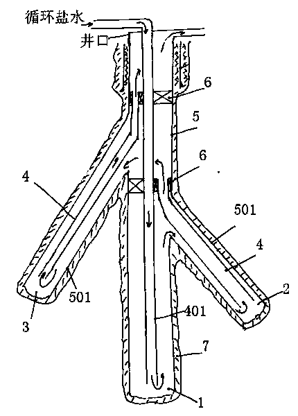
[0061] Step 1: The injected circulating brine enters the No. 1 wellbore 1 through the uncoupled tubing 401;
[0062] Step 2: The circulating brine reaches the bottom of the No. 1 wellbore 1, enters the annulus between the casing 5 and the uncoupled tubing 401, and returns upward;
[0063] Step 3: The returned circulating brine passes through the tubing 4 and the annulus of the No. 2 wellbore 2, and reaches the bottom of the No. 2 wellbore 2;
[0064] Step 4: The circulating brine after reaching the bottom of No. 2 well hole 2 passes through the tubing 4 and flows back upwards;
[0065] Step 5: The circulating brine after flowback passes through the annulus between the tubing 4 and the No. 3 wellbore 3, and enters the bottom of the No. 3 wellbore 3;
[0066] Step 6: The circulating brine that reaches the bottom of No. 3 borehole 3 flows back upwards to the ...
Embodiment 3
[0077] On the basis of the foregoing embodiments, the specific steps adopted in this embodiment are as follows:
[0078] 1. Select a well location in the geothermal enrichment area;
[0079] 2. Use a Φ346mm drill bit to start drilling (first opening), drill 500 meters, and pull out the drill;
[0080] Drill structure:
[0081] Φ346mm drill bit + Φ203mm screw + Φ195mm non-magnetic drill collar + MWD + 3 Φ203mm drill collars + 15 Φ177.8mm drill collars + Φ88.9mm heavy drill pipe (15 pieces) + Φ88.9mm drill pipe
[0082] Among them, drill pressure: 120-180KN revolution: 50-60+ screw pump pressure: 5-6MPa
[0083] Displacement: 38-42L / S
[0084] 3. Lower the Φ273.3mm casing, inject cement slurry into the casing for circulation, consolidate the Φ273.3mm casing and the formation together, and wait for 12-24 hours. Cement slurry properties: density 1.75g / cm 3 Initial consistency: <30 Bc
[0085] 4. Secondary spud drilling with Φ241.3mm drill bit,
[0086] Drill structure:
...
PUM
 Abstract
Description
Claims
Application Information