
Cylinder-cover-free engine with novel crankshaft-connecting-rod mechanism

A crankshaft connecting rod and engine technology, applied in the direction of machines/engines, combustion engines, mechanical equipment, etc., can solve the problems of insufficient fuel combustion, difficult quality assurance, and inability to work continuously, etc., to achieve increased oxygen, simple structure, and reliable operation Effect

Active Publication Date: 2017-01-04
梁廷容
View PDF6 Cites 4 Cited by
  • Summary
  • Abstract
  • Description
  • Claims
  • Application Information

AI Technical Summary

Problems solved by technology

The conventional crankshaft is one of the core components of the traditional engine, which has many insurmountable shortcomings, such as complex design and manufacture, difficult quality assurance, high requirements for manufacturing materials, limitations in increasing power and improving work efficiency, high manufacturing costs, installation and maintenance difficulties, short service life, etc.
[0005] (3) Insufficient combustion of fuel in the cylinder, serious exhaust pollution, high fuel consumption and low thermal efficiency
[0006] (4) The cylinder cannot establish an effective lubrication system, the heat dissipation is poor, the parts wear heavily, and it cannot work continuously

Method used


Image

  • Cylinder-cover-free engine with novel crankshaft-connecting-rod mechanism
  • Cylinder-cover-free engine with novel crankshaft-connecting-rod mechanism
  • Cylinder-cover-free engine with novel crankshaft-connecting-rod mechanism

Examples


Embodiment Construction

[0028] The present invention will be further described below in conjunction with the accompanying drawings.

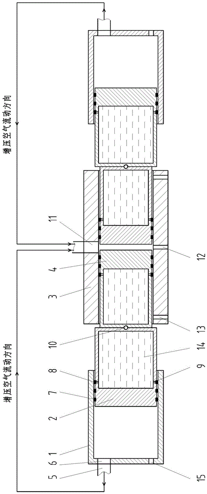
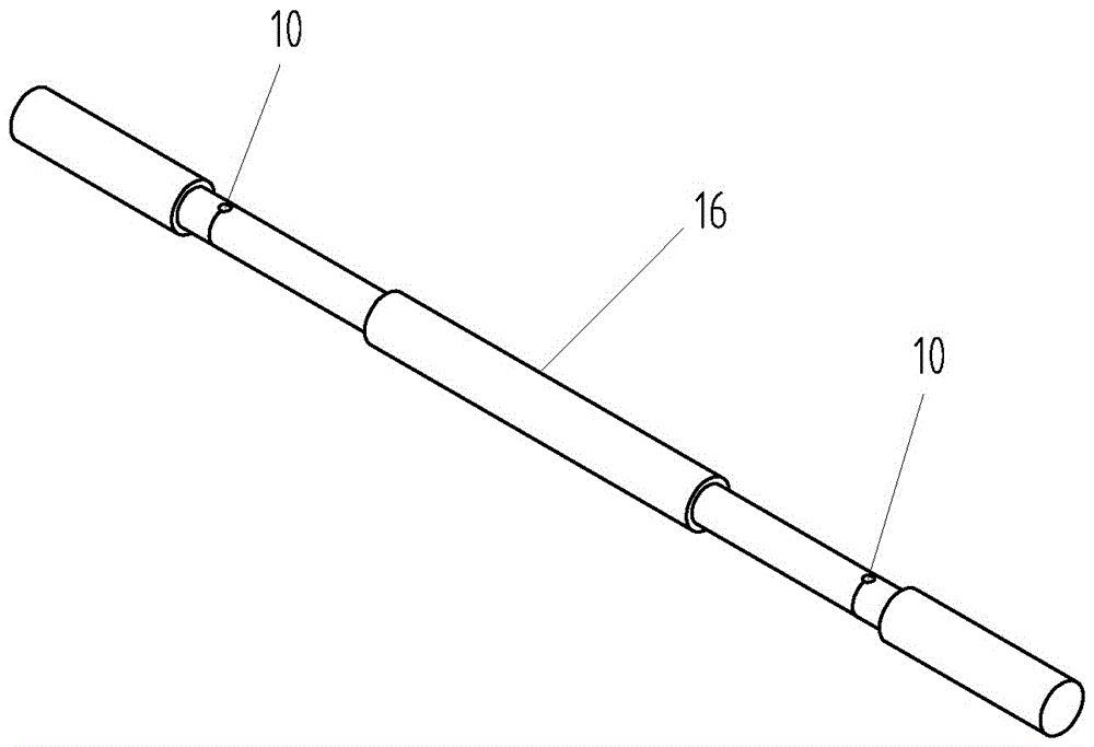
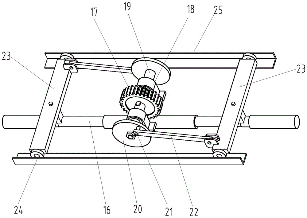
[0029] Such as image 3As shown, the power output unit of the engine of the present invention comprises a novel crankshaft connecting rod mechanism, power output gear 17 and cylinder opposing device 16; Plate 23; the power output gear 17 is fixedly installed in the middle of the straight shaft 19, the centers of the two round wheels 20 are respectively fixedly connected to the two ends of the straight shaft 19, and the two round wheels 20 are provided with protruding outwards at the edge of the disk surface. The eccentric pins 21 of the two eccentric pins 21 are opposite to the positions on the disc surfaces of the two round wheels 20; the two sides of the straight shaft 19 are each provided with a rail-fixing plate 23 parallel to the straight shaft 19, and the eccentricity of the two round wheels 20 Pin shafts 21 are respectively articulated with one end of two conne...


PUM


Abstract

The invention provides a cylinder-cover-free engine with a novel crankshaft-connecting-rod mechanism. A power output unit of the engine comprises the novel crankshaft-connecting-rod mechanism, a power output gear and an air cylinder opposition device. The novel crankshaft-connecting-rod mechanism comprises a straight shaft, round wheels, connecting rods and fixed track plates. The two fixed track plates are driven by the air cylinder opposition device to do opening and closing reciprocating linear movement, and then the two connecting rods are driven to simultaneously conduct pushing drive and pulling drive on the round wheels at the two ends of the straight shaft correspondingly in the opposite directions, so that the two round wheels drive the straight shaft and the power output gear to rotate continuously. According to the engine, the novel crankshaft-connecting-rod mechanism which is simple in structure and reliable in operation is used for replacing conventional crankshaft-connecting-rod mechanisms with many defects, and the advanced air cylinder opposition device is adopted for driving; and an acting air cylinder of the air cylinder opposition device is not provided with a cylinder cover, automatic supercharging can be achieved while the air cylinder acts, the displacement can be flexibly changed, the fuel conversion efficiency is remarkably improved, and the two problems of lubrication and complete air exchange of conventional engines are effectively solved.

Description

technical field [0001] The invention relates to a reciprocating piston internal combustion engine, in particular to a cylinder headless engine with a novel crankshaft connecting rod mechanism and a cylinder opposing device. Background technique [0002] The traditional two-stroke diesel engine has the following disadvantages: [0003] (1) The cylinder head of a traditional engine has many accessories, takes up a lot of space, is complicated to install and debug, and has high noise and vibration during operation. [0004] (2) Adopt conventional crankshaft and connecting rod mechanism for transmission. The conventional crankshaft is one of the core components of the traditional engine, which has many insurmountable shortcomings, such as complex design and manufacture, difficult quality assurance, high requirements for manufacturing materials, limitations in increasing power and improving work efficiency, high manufacturing costs, installation And maintenance difficulties, sh...

Claims


Application Information

Patent Timeline
Patent Type & Authority Applications(China)
IPC IPC(8): F02B75/28F02B33/06F02B75/18F16H21/18
CPCF02B33/06F02B75/18F02B75/282F02B2075/1812F16H21/18
Inventor 梁廷容
Owner 梁廷容
Learn More