Viewer illumination equipment

A lighting equipment and film viewing technology, which is applied in the field of medical equipment, can solve the problems of multi-environment, multi-purpose use, single function of the film viewer, eye fatigue, etc., and achieve the effect of alleviating eye fatigue, uniform light emission and soft light

Inactive Publication Date: 2017-01-04
马东阁
View PDF7 Cites 2 Cited by
  • Summary
  • Abstract
  • Description
  • Claims
  • Application Information

AI Technical Summary

Problems solved by technology

[0002] At present, the X-ray photographic film and CT imaging film viewing lights commonly used in domestic medical institutions are traditional box-type film viewing lights. The light source of this film viewing light is generally provided by fluorescent lamps. The flashing frequency of fluorescent lamps is only 50Hz. The flicker is strong, long-term use will cause serious damage to the eyes of the viewer, and its ultraviolet and infrared radiation is easy to cause eye fatigue
In addition, since the strong light emitted by fluorescent lamps enters the eyes of the human body through various channels, it will cause dizziness, blurring, and glare to the eyes, and it will also cause great damage to the eyes if used for a long time
Later, LED film viewers appeared on the market. Compared with fluorescent lamps, their radiant heat is relatively low, but there is still a certain amount of radiant heat. In addition, LED light sources contain a large amount of blue light components, and there are also serious problems such as glare and glare, which are easy to cause eyesight. Fatigue, long-term use will cause damage to the eyes
Moreover, the current film viewer has a single function, which is difficult to meet the multi-environment and multi-purpose use

Method used


Image

  • Viewer illumination equipment

Examples


Embodiment Construction

[0024] In order to make the objectives, technical solutions and advantages of the present invention clearer, the present invention will be further described in detail below with reference to specific embodiments and accompanying drawings.

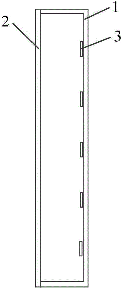
[0025] figure 1 is a schematic structural diagram of a film viewing lighting device according to an embodiment of the present invention, such as figure 1 As shown, the film viewing lighting equipment includes: a casing 1, a light-transmitting device 2, and a light source 3, wherein:

[0026] The light-transmitting device 2 is installed on the front side of the housing 1;

[0027] The light source 3 is installed in the sealed space formed by the housing 1 and the light-transmitting device 2 , for example, it can be fixedly connected with the housing 1;

[0028] The light source 3 includes one or more OLEDs.

[0029] In an embodiment of the present invention, the OLED includes an OLED light-emitting panel, an OLED driving circuit and a con...


PUM


Abstract

The invention discloses viewer illumination equipment, which comprises a casing, a light transmission device and a light source, wherein the light transmission device is arranged on the front side of the casing; the light source is arranged in a sealed space formed by the casing and the light transmission device; the light source comprises one or a plurality of OLEDs (optical light emitting diodes). The viewer illumination equipment uses the OLEDs as illumination light source; the OLED light source is a surface light source; the illumination coverage area is large; the illumination is uniform; the color temperature is adjustable; the emission spectrum is similar to natural light; the content of harmful blue light and ultraviolet light is very small; the injury on eyes can be effectively reduced; the eye fatigue can be relieved; in addition, the viewer illumination equipment also has the functions of portability, self power supply, data transmission and the like. Generally, the viewer illumination equipment can meet the requirements of a general viewer lamp, can protect the eyes from being injured, can also be used in various environments such as indoor environments and open air environments, and can also provide multi-purpose use at the same time.

Description

technical field [0001] The invention relates to the field of medical instruments, in particular to a film viewing lighting device. Background technique [0002] At present, the X-ray film and CT imaging film viewing lamps commonly used in domestic medical institutions are traditional box-type viewing lamps. The light source of this viewing lamp is generally provided by fluorescent lamps. The flickering sensation is strong, and long-term use will cause serious damage to the eyes of the viewing doctor, and its ultraviolet and infrared radiation can easily cause eye fatigue. In addition, since the strong light emitted by the fluorescent lamp enters the human eyes through various ways, it will bring dizziness, blurred vision and dazzling feeling to the eyes, and long-term use will also cause great damage to the eyes. Later, LED film viewing lamps appeared on the market. The radiant heat is lower than that of fluorescent lamps, but there is still a certain amount of radiant heat...

Claims


Application Information

Patent Timeline
Patent Type & Authority Applications(China)
IPC IPC(8): G02B27/02
CPCG02B27/024
Inventor 马东阁马远博
Owner 马东阁
Why Eureka
Try Eureka