A piezoelectric energy harvesting system and its control method

A piezoelectric energy collection system technology, applied in piezoelectric effect/electrostrictive or magnetostrictive motors, electrical components, generators/motors, etc. Problems such as circuit energy can only be stored and used

Active Publication Date: 2018-04-03
NANJING LOW POWER IC TECH INST CO LTD
View PDF4 Cites 0 Cited by
  • Summary
  • Abstract
  • Description
  • Claims
  • Application Information

AI Technical Summary

Problems solved by technology

However, the shortcomings of this structure include that the voltage ripple at the end of the energy storage unit is very large, and it is directly used as the power supply of the DC-DC converter, which will inevitably affect the performance of the circuit; there is no power supply self-starting pre-charging circuit in this structure, so once the power supply When the voltage is very low or the external vibration energy is weak, the entire energy harvesting system cannot work; in addition, when there is abundant external vibration energy, the energy in the load circuit can only be stored and used, and the remaining excess energy is not available. It is stored in time by other large capacitors or battery devices, so that when the vibration energy in the environment is weak, the energy harvesting system can continue to work and provide energy for the load circuit

Method used


Image

  • A piezoelectric energy harvesting system and its control method
  • A piezoelectric energy harvesting system and its control method
  • A piezoelectric energy harvesting system and its control method

Examples


Embodiment Construction

[0033] The technical solutions of the present invention will be described in detail below in conjunction with the accompanying drawings.

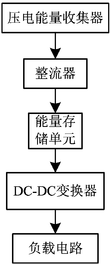
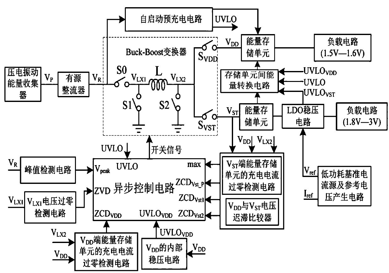
[0034] Such as figure 2 As shown, the piezoelectric energy harvester converts the vibration energy generated by the piezoelectric material into AC power and inputs it into the active rectifier, and the active rectifier converts the AC power into DC energy and outputs a voltage V R , if the system supply voltage V DD Below 1V, the output energy of the rectifier will enter through the self-starting pre-charging circuit VDD end of the energy storage unit, the voltage V DD increases continuously, once the voltage V DD If it is higher than 1.08V, the self-starting pre-charging circuit will be turned off, and the system will enter the piezoelectric energy extraction mode, and all the output energy of the rectifier will enter the Buck-Boost converter. According to the peak detection circuit, its input voltage V R Peak detection, output a risi...


PUM


Abstract

The invention discloses a piezoelectric energy collection system and a control method thereof. The piezoelectric energy collection system comprises a piezoelectric energy collector, an active rectifier, a Buck-boost converter, an asynchronous control circuit, a self-startup precharge circuit, a peak detection circuit, an inductance input-end voltage zero-crossing detection circuit, a VDD-end energy storage unit, a charge current zero-crossing detection circuit of the VDD-end energy storage unit, a VST-end energy storage unit, a charge current zero-crossing detection circuit of the VST-end energy storage unit, an inter-storage-unit energy conversion circuit, an LDO voltage-stabilizing circuit, a VDD internal voltage-stabilizing circuit and a low-power reference current source and reference voltage generation circuit. According to the invention, an ultralow-power design technology is introduced, a conventional circuit structure is improved, performance optimization and structural innovation are performed on each circuit module, static power consumption of the whole circuit system is reduced to 111.1nW, and the energy conversion efficiency is as high as 89.4%. Besides, the system also has the advantages of small chip area, high integration, complete automation, high adaptive capacity to environment and the like.

Description

technical field [0001] The invention belongs to the technical field of micro-energy collection, and in particular relates to a piezoelectric energy collection system and a control method thereof. Background technique [0002] At present, the traditional battery power supply method of wireless sensor nodes has the problems of limited storage capacity and short life, and regular battery replacement will greatly increase the cost. The natural environment is full of a lot of environmental energy, such as wind energy, solar energy, thermal energy and vibration energy. And because vibration energy is a widely existing form of energy, harvesting vibration energy through piezoelectric energy transducers has universal significance and broad application prospects. [0003] figure 1 It is a structural block diagram of a typical piezoelectric energy harvesting system. The piezoelectric energy harvester converts the vibration energy generated by the piezoelectric material into AC power...

Claims


Application Information

Patent Timeline
Patent Type & Authority Patents(China)
IPC IPC(8): H02N2/18
CPCH02N2/18H02N2/181
Inventor 张长春王兆悦郭宇锋
Owner NANJING LOW POWER IC TECH INST CO LTD
Why Eureka
Try Eureka