Supercharge Your Innovation With Domain-Expert AI Agents!

Automatic blockage elimination system of filter stick conveying equipment

A kind of conveying equipment and automatic technology, which is applied in the direction of conveyor, transportation and packaging, etc. It can solve the problems of filter stick blockage at the receiving station, high labor intensity, and production line shutdown, so as to reduce material waste, reduce industrial accidents, and reduce labor intensity of workers Effect

Active Publication Date: 2017-01-11
苏州沪琨智能科技有限公司
View PDF7 Cites 1 Cited by
  • Summary
  • Abstract
  • Description
  • Claims
  • Application Information

AI Technical Summary

Problems solved by technology

The processed filter rods are transported through the channel, loaded and unloaded, etc. When they are sent to the launch station, there are a certain proportion of filter rods with poor quality. These filter rods with quality defects are launched by the launch station and pneumatically conveyed After the pipeline reaches the receiving station, it is easy to cause blockage of the filter rod in the receiving station
When the blockage occurs, the receiving station stops and sends a signal to the transmitting station at the same time, and the transmitting station stops transmitting, but the filter rods in the pneumatic conveying pipeline continue to move forward under the action of inertia and compressed air, causing a large number of filter rods to be blocked in the pipeline
The filter rods in the pipeline are squeezed and deformed due to the close arrangement of the front and back. Therefore, after the fault of the filter rod blockage in the receiving station is eliminated, before restarting the machine, if the filter rods with quality defects in the pipeline are not discharged in time, it is easy to cause the receiving station. Station again filter plug clogged
At present, the method of discharging the clogged filter rods in the pipeline is to rely on manual operation, which is labor-intensive and has certain dangers, sometimes causing the production line to be forced to stop

Method used


Image

  • Automatic blockage elimination system of filter stick conveying equipment
  • Automatic blockage elimination system of filter stick conveying equipment
  • Automatic blockage elimination system of filter stick conveying equipment

Examples


Embodiment Construction

[0018] The present invention will be further described below in conjunction with the accompanying drawings and specific embodiments.

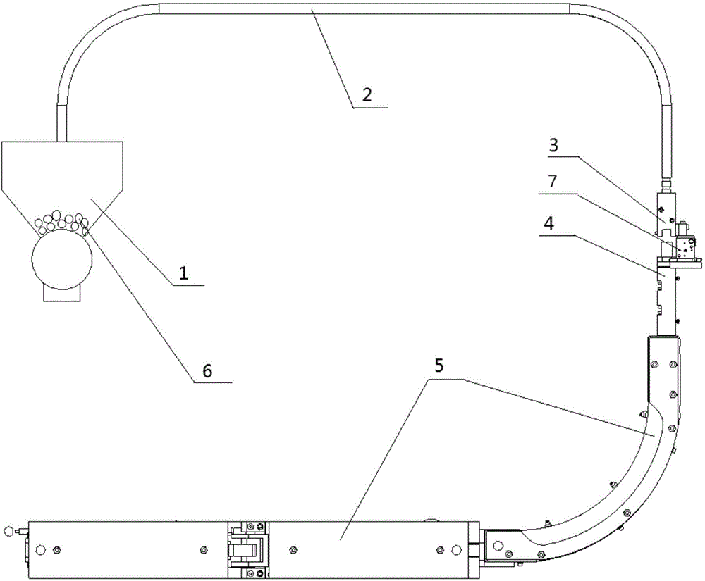
[0019] figure 1 It is a structural diagram of the automatic blockage removal system of the filter rod conveying equipment.

[0020] Such as figure 1 As shown, the automatic clogging removal system of the filter rod conveying equipment includes a launching station 1 , a pneumatic conveying pipeline 2 , a pipeline clamping device 7 , a pipeline blocking device 3 , a clogging sensor 4 and a receiving station 5 .

[0021] One end of the pneumatic conveying pipeline 2 is connected with the transmitting station 1 , and the other end is connected with the receiving station 5 . The filter rod 6 is arranged in the launch station 1 . In the normal working state, the transmitting station 1 transports the filter rod 6 to the pneumatic conveying pipeline 2 through compressed air, and finally the filter rod 6 arrives in the receiving station 5 .

[0022]...


PUM


Abstract

The invention provides an automatic blockage elimination system of filter stick conveying equipment. One end of a pneumatic conveying pipeline is connected with a launch station, and the other end of the pneumatic conveying pipeline is connected with a receiving station. A pipeline blocking device is arranged on the pneumatic conveying pipeline and divides the pneumatic conveying pipeline into two segments. When a blockage inductor does not induct blockage, the pneumatic conveying pipeline is divided into the two segments which are in butt joint. When the blockage inductor inducts blockage, the pneumatic conveying pipeline is divided by the pipeline blocking device into the two segments which are not in butt joint. The automatic blockage elimination system has the beneficial effects that when blockage of pipeline filter sticks occurs, the system can be automatically started, the pipeline is blocked, convenience is provided for discharging the blocked filter sticks in the pipeline, and the system can automatically reset after the filter sticks are discharged; the problem that pipeline filter stick blockage is eliminated manually at present is thoroughly solved; and the aspects of improving the equipment automation level, reducing the labor intensity of workers, reducing industrial accidents, improving the equipment operating efficiency, reducing material waste and the like are obviously improved.

Description

technical field [0001] The invention relates to filter rod conveying equipment, which is an automatic blockage removal device for the filter rod conveying equipment. Background technique [0002] The filter rod conveying equipment includes a launching station, a receiving station and pneumatic conveying pipelines connecting the launching station and the receiving station. The processed filter rods are transported through the channel, loaded and unloaded, etc. When they are sent to the launch station, there will be a certain proportion of filter rods with poor quality. After the pipeline reaches the receiving station, it is easy to cause blockage of the filter rod in the receiving station. When blockage occurs, the receiving station shuts down and sends a signal to the transmitting station at the same time, and the transmitting station stops transmitting, but the filter rods in the pneumatic conveying pipeline continue to move forward under the action of inertia and compress...

Claims


Application Information

Patent Timeline
IPC IPC(8): B65G51/36B65G51/32
Inventor 王鑫
Owner 苏州沪琨智能科技有限公司
Features
  • R&D
  • Intellectual Property
  • Life Sciences
  • Materials
  • Tech Scout
  • Unparalleled Data Quality
  • Higher Quality Content
  • 60% Fewer Hallucinations
Learn More