Power generation system utilizing waste heat of high-temperature flue gas

A power generation system, high-temperature flue gas technology, applied in the steam generation method using heat carrier, preheating, liquid degassing, etc., can solve the problems of high cost of system transformation, low efficiency of waste heat utilization, etc., to improve work ability, The effect of increasing power generation and improving waste heat utilization efficiency

Active Publication Date: 2017-01-11
CITIC HEAVY INDUSTRIES CO LTD
View PDF5 Cites 8 Cited by
  • Summary
  • Abstract
  • Description
  • Claims
  • Application Information

AI Technical Summary

Problems solved by technology

[0005] The purpose of the present invention is to provide a power generation system using high-temperature flue gas waste heat to solve the problems of low waste heat utilization efficiency and high system transformation cost

Method used


Image

  • Power generation system utilizing waste heat of high-temperature flue gas

Examples


Embodiment Construction

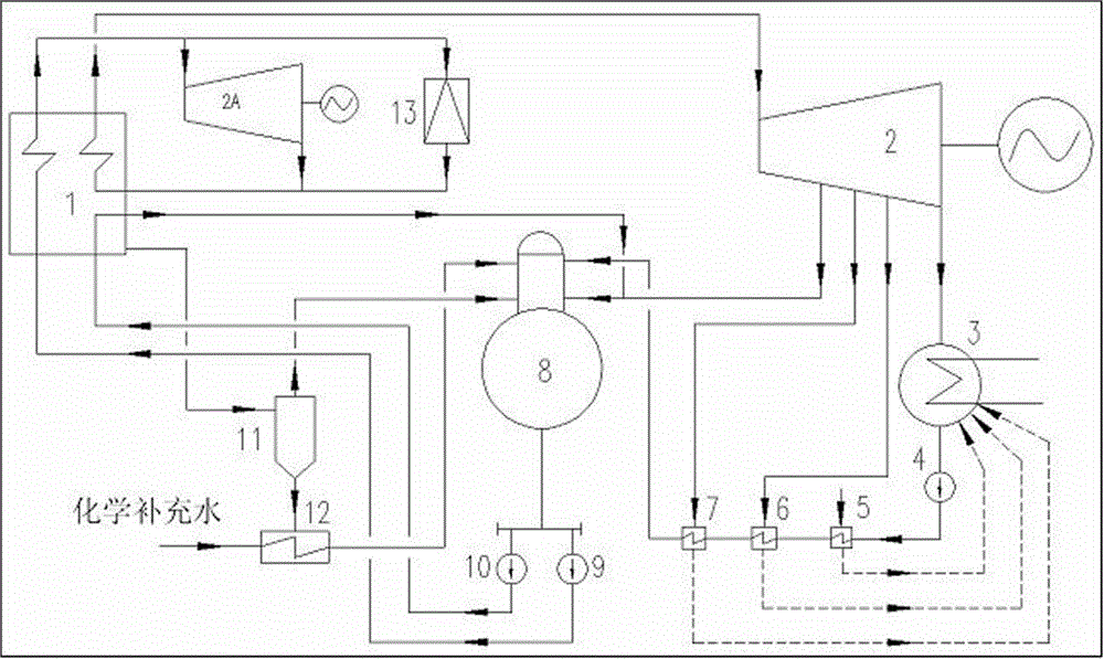
[0027] As shown in the figure, the specific implementation method is as follows:

[0028] A power generation system using high-temperature flue gas waste heat, including a dual-pressure waste heat boiler 1 with a reheater inside, characterized in that: the high-pressure steam of the double-pressure waste heat boiler 1 is passed into a back-pressure steam turbine generator set 2A for power generation , the steam generated by the back-pressure turbo-generator unit 2A returns to the dual-pressure waste heat boiler 1 to be heated by the reheater, and the reheated steam enters the turbo-generator unit 2 through the steam pipeline to generate power. The turbo-generator unit 2. The steam after power generation is passed into the condenser 3, and the condensed water formed in the condenser 3 is passed through the condensed water pump 4 into the steam seal heater 5, the first-level low-pressure heater 6 and the second-level low-pressure heater 7 for heating , the heated condensed water...


PUM


Abstract

A power generation system utilizing waste heat of high-temperature flue gas comprises a dual-pressure waste heat boiler with a reheater arranged therein, wherein high-pressure steam of the dual-pressure waste heat boiler is pumped into a back-pressure turbo generator set to conduct power generation; steam obtained after power generation of the turbo generator set returns to the dual-pressure waste heat boiler to be heated by the reheater; and the reheated steam passes through a steam pipeline and enters the turbo generator set for power generation. The power generation system is provided with the dual-pressure waste heat boiler, which utilizes waste heat to produce high-temperature high-pressure or ultrahigh-pressure main steam and low-pressure steam and has the reheating function, and the main steam produced by the waste heat boiler is used for power generation through the high-temperature high-pressure or ultrahigh-pressure back-pressure turbo generator set.

Description

technical field [0001] The invention relates to the technical field of waste heat power generation, in particular to a power generation system utilizing waste heat of high-temperature flue gas. Background technique [0002] The high-temperature flue gas waste heat generated by high-temperature waste heat industries such as clean coke ovens and industrial silicon is used to generate electricity, and the power of the turbogenerator is relatively small. In the past, due to the limitation of equipment manufacturing technology, medium-temperature, medium-pressure or sub-medium-pressure steam parameters were often used. The power generation efficiency is low, the self-consumption rate is high, the circulating water consumption is large, and the economic benefit of the enterprise is poor. [0003] At present, with the advancement of technology and the improvement of equipment manufacturing technology, the manufacture of high-parameter and low-power turbogenerator sets is becoming m...

Claims


Application Information

Patent Timeline
Patent Type & Authority Applications(China)
IPC IPC(8): F01K11/02F01K7/38F22B1/18F22D1/32F22D1/50
CPCF01K7/38F01K11/02F22B1/18F22D1/32F22D1/50Y02P80/15
Inventor 彭岩刘怀亮仝伟峰时小宝王新建吴梦
Owner CITIC HEAVY INDUSTRIES CO LTD
Why Eureka
Try Eureka