Supercharge Your Innovation With Domain-Expert AI Agents!

Solar energy engineering header

A solar energy and engineering technology, applied in the direction of solar thermal energy, solar thermal power generation, solar thermal collectors, etc., can solve the problems of affecting the appearance, unevenness, trouble removal, etc., to save construction costs and materials, improve work efficiency, save money The effect of going to the installation space

Inactive Publication Date: 2017-01-11
SHANDONG HUALIN NEW ENERGY EQUIP
View PDF5 Cites 0 Cited by
  • Summary
  • Abstract
  • Description
  • Claims
  • Application Information

AI Technical Summary

Problems solved by technology

Most of the existing solar engineering header end caps are relatively simple in structure, and they are directly buckled on the outer edge of the outlet when they are connected to the outlet, so the connection is not firm, and it is easy to fall off during transportation and installation, which affects the use
Most of the end caps are square or with tapered corners, which is not easy to place
Due to the thin bottom edges on both sides of the bottom of the shell, it is easy to scratch the operator during installation and transportation
It is inevitable that the foaming of the engineering header will be uneven during the production process, and the foam will easily overflow from the end cap, which not only affects the appearance, but also is troublesome to remove
Generally, the diameter of the water inlet and outlet of the inner pipe of the solar energy engineering header is relatively small, and the internal liquid flow is easily affected. The position of the water inlet and outlet is tightened by screws, and the outlet and the inner pipe are not an integral structure. Leakage phenomenon, and the strength is not high enough, the pressure resistance is weak

Method used


Image

  • Solar energy engineering header
  • Solar energy engineering header
  • Solar energy engineering header

Examples


Embodiment Construction

[0019] The present invention will be further described below in conjunction with specific examples. It should be understood that these examples are only used to illustrate the present invention and are not intended to limit the scope of the present invention. In addition, it should be understood that after reading the teachings of the present invention, those skilled in the art can make various changes or modifications to the present invention, and these equivalent forms also fall within the scope defined by the appended claims of the application.

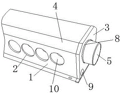
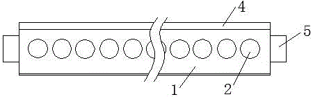
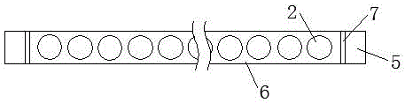
[0020] see figure 1 It is a three-dimensional view of the structure of the present invention, see figure 2 It is the front view of the structure of the present invention, see image 3 It is the front view of the liner structure of the present invention, see Figure 4 It is the right view of the structure of the present invention. The solar energy engineering header of this structure includes an outer shell 1, an inner tank insta...


PUM


Abstract

The invention discloses a solar energy engineering header. The solar energy engineering header comprises an outer shell, an inner container, vacuum heat collection tube holes, a foaming layer and end covers. Two opposite side faces of the outer shell and two opposite side faces of the inner container are each provided with the corresponding vacuum heat collection tube holes. The left corner and the right corner of the top of the cross section of shell and the left corner and the right corner of the top of the cross section of each end cover are arranged to be edged corners. The inner container comprises a tube inner segment and water inlets / outlets formed in the two ends of the tube inner segment. An opening of each water inlet / outlet is in a round shape. The cross section of the tube inner segment is square. The inner container is of a structure with the tube inner segment and the water inlets / outlets integrally formed. Reinforcing ribs are arranged at the intersection positions of the water inlets / outlets and the tube inner segment. Each water inlet / outlet of the inner container penetrates the hollow part of the corresponding end cover and is arranged outside the outer shell. Foaming vent holes are further formed in the end covers. A dustproof ring is arranged at the rim of the hollow part in the middle of each end cover. Multiple pin bolts are arranged at the inner side of each end cover. The end covers are inserted into the foaming layer through the pin bolts and are tightly connected with the two ends of the outer shell. The solar energy engineering header is simple in structure, capable of improving work efficiency, high in strength and safe and convenient to use; the water leakage phenomenon cannot occur; and all components are connected tightly.

Description

technical field [0001] The invention relates to the technical field of solar engineering headers, in particular to solar engineering headers. Background technique [0002] The solar engineering header is an important part of the solar water heating engineering, which is used to collect and store solar heat. It is composed of a shell, an inner tank with a foam body, and an end cover. The outlet water temperature can be set at will according to needs, and it can cooperate with conventional energy sources to realize a semi-instantaneous solar water heating system with 24-hour continuous hot water supply. Most of the existing solar energy engineering header end caps are relatively simple in structure, and are directly buckled on the outer edge of the outlet when they are connected to the outlet, so that the connection is not firm, and it is easy to drop during transportation and installation, which affects the use. Most of the end caps are square or have tapered corners, which ...

Claims


Application Information

Patent Timeline
IPC IPC(8): F24J2/46
CPCY02E10/40F24S80/00
Inventor 王恩明王银环蒋劲松高长东
Owner SHANDONG HUALIN NEW ENERGY EQUIP
Features
  • R&D
  • Intellectual Property
  • Life Sciences
  • Materials
  • Tech Scout
  • Unparalleled Data Quality
  • Higher Quality Content
  • 60% Fewer Hallucinations
Learn More