Passive descaling type evaporative cooler

An evaporative cooler and evaporative cooling technology, which is used in the cleaning of rotating equipment, cleaning heat transfer devices, lighting and heating equipment, etc. The effect of spark contact with gas, safe descaling operation, avoidance of explosion hazard

Inactive Publication Date: 2017-01-11
CISDI ENG CO LTD +1
View PDF8 Cites 4 Cited by
  • Summary
  • Abstract
  • Description
  • Claims
  • Application Information

AI Technical Summary

Problems solved by technology

[0004] In view of the shortcomings of the prior art described above, the purpose of the present invention is to provide a passive descaling evaporative cooler, which is used to solve the difficulty of descaling the inner wall of the evaporative cooler in the prior art, short service life, affecting production efficiency, maintenance Difficulty, high cost, etc.

Method used


Image

  • Passive descaling type evaporative cooler
  • Passive descaling type evaporative cooler
  • Passive descaling type evaporative cooler

Examples


Embodiment 2

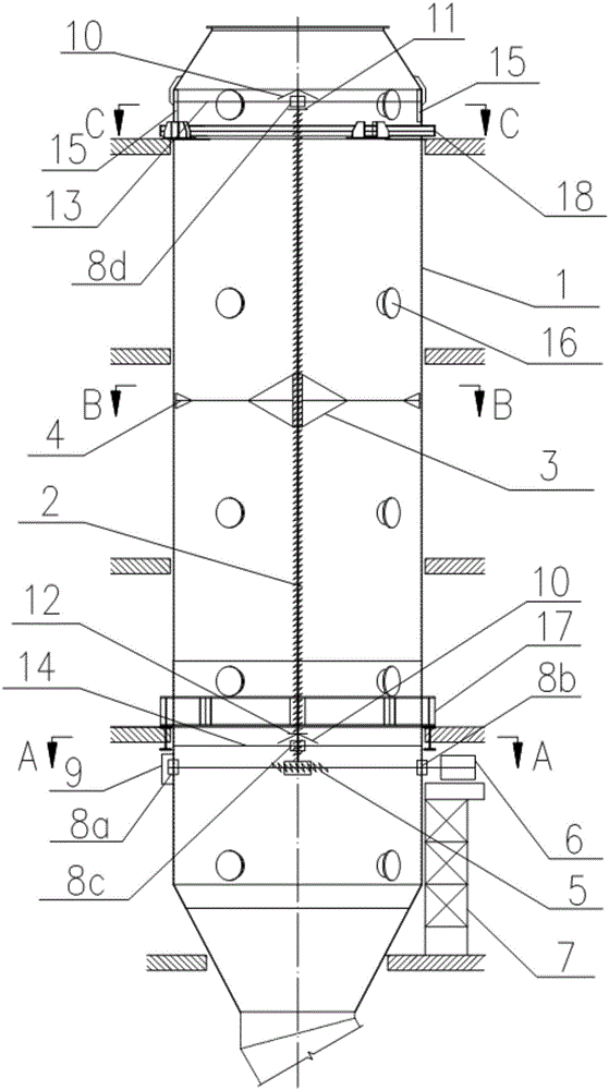
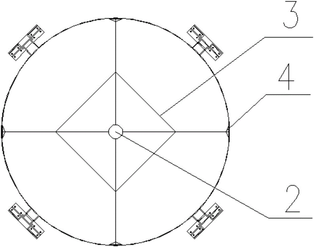
[0061] like Figure 5 As shown, the descaling device includes a knife support frame 3 and a descaling knife 4, the descaling knife 4 is installed on the support mechanism 2 through the knife support frame 3, the descaling knife 4 is arranged along the axial direction of the evaporative cooling cylinder 1, and the descaling The length of the cutting edge of the knife 4 matches the length of the evaporative cooling cylinder 1, and the driving mechanism 6 drives the descaling device to rotate along the circumferential direction of the evaporative cooling cylinder 1 for descaling. The knife support frame 3 is fixedly connected with the support mechanism 2, and the descaling knife 4 is installed on the peripheral end of the knife support frame 3. The knife support frame 3 adopts a frame structure, and the number of descaling knives 4 is along the evaporative cooling cylinder 1 according to requirements. Arranged in the circumferential direction, the support mechanism 2 drives the k...

Embodiment 3

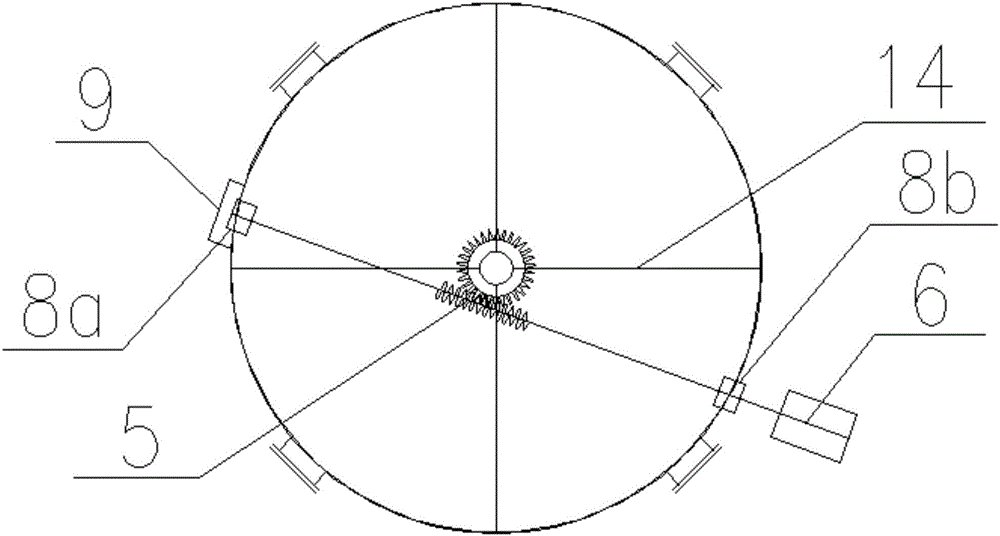
[0063] like Image 6 and Figure 7 As shown, the descaling device includes a knife support frame 3 and a descaling knife 4. The descaling knife 4 is installed on the support mechanism 2 through the knife support frame 3. The descaling knife 4 is arranged along the circumference of the inner wall of the evaporative cooling cylinder 1, and at least Covering its inner circumference, that is, the circumferential circle of the knife support frame 3 is covered with descaling knives, and the cutting edge of the descaling knife is arranged in a circle, so that the descaling knife is in full contact with the inner wall of the evaporative cooling cylinder 1 in the circumferential direction, The descaling knife 4 on the knife support frame 3 is provided with at least one circle, and the number of circles of the descaling knife 4 can be adjusted as required. The driving mechanism 6 drives the descaling device to move along the axial direction of the evaporative cooling cylinder 1 for des...

Embodiment 1

[0064] The operating steps of embodiment one and embodiment three are:

[0065] 1) Before the converter oxygen blowing starts, the knife support frame 3 stops at the limit device 12 at the lower end of the support mechanism 2;

[0066] 2) After the converter starts tapping, the drive mechanism 6 runs, the support mechanism 2 drives the knife support frame 3 to rotate from bottom to top through the screw drive, and the descaling knife 4 at the end of the knife support frame 3 scrapes off the inner wall of the evaporative cooling cylinder 1 Dust, the knife support frame 3 moves upward until the upper limit device 11 of the support mechanism 2 . Then the drive mechanism 6 reverses, driving the knife support frame 3 to rotate from top to bottom.

[0067] 3) Before the oxygen blowing of the converter starts, the knife support frame 3 rotates back to the starting position, that is, stops at the limit device 12, and completes one descaling, one descaling for each furnace of steel, a...


PUM


Abstract

The invention relates to the field of environmental protection equipment, in particular to a passive descaling type evaporative cooler. The passive descaling type evaporative cooler is used for descaling of the inner walls of evaporative coolers or easy-to-scale barrels in converter gas purification and recovery systems in the metallurgical industry. The passive descaling type evaporative cooler comprises an evaporative cooling barrel, and further comprises a drive mechanism, a descaling device and a supporting mechanism used for mounting of the descaling device. The descaling device is arranged in the evaporative cooling barrel. The drive mechanism drives the descaling device through the supporting mechanism to move in the axial direction and / or the circumferential direction of the evaporative cooling barrel to carry out descaling on the inner wall of the evaporative cooling barrel. The passive descaling type evaporative cooler has the beneficial effects that descaling of the interior of the evaporative cooling barrel is achieved through the descaling device; the structure is simple; operation is stable; the service life of equipment is prolonged; descaling is simple and convenient; dirt recycling is facilitated; pollution and waste are reduced; and energy saving and environment protection are achieved.

Description

technical field [0001] The invention relates to the field of environmental protection equipment, in particular to a passive descaling evaporative cooler, which is used for descaling the evaporative cooler or the inner wall of a cylinder prone to fouling in a converter gas purification and recovery system in the metallurgical industry. Background technique [0002] In the converter gas purification and recovery system in the metallurgical industry (the converter gas purification and recovery system uses the LT method for gas purification and recovery, and the LT method is also called the dry method), an evaporative cooler with a cylindrical structure is used in the system. The general layout of the equipment in the converter gas purification and recovery plant is as follows: a spray gun is installed at the end of the waste heat boiler before the evaporative cooler. After the heat and mass exchange between the gas and water mist and water vapor, the temperature of the flue gas...

Claims


Application Information

Patent Timeline
IPC IPC(8): F28G3/10F28G15/00F28G15/04
CPCF28G3/10F28G15/003F28G15/04
Inventor 桑杭武梁广周涛张斌王树乾
Owner CISDI ENG CO LTD
Why Eureka
Try Eureka