
Machine vision LED illuminating apparatus for color discrimination

A technology of LED lighting and machine vision, applied in measurement devices, color/spectral characteristic measurement, instruments, etc., can solve the problems that do not involve light source color rendering index, color temperature and illumination uniformity, image color feature distortion, can not meet technical requirements, etc. problem, to achieve the effect of easy application and promotion, reduce distortion, and ensure long-term stability

Inactive Publication Date: 2017-01-11
SHANGHAI DIANJI UNIV
View PDF9 Cites 2 Cited by
  • Summary
  • Abstract
  • Description
  • Claims
  • Application Information

AI Technical Summary

Problems solved by technology

[0004] Suppliers of machine vision light sources at home and abroad mainly include Japan CCS, American AI, Daheng Image, Opto, etc. Their light sources can only meet the industrial needs of specific applications. For example, using blue LED chips to excite phosphors can emit 6500K The cool white light on the observation surface is basically uniform, but its general color rendering index Ra is less than 80, resulting in large distortion of image color characteristics, which cannot meet the technical needs of emerging markets in the field of color recognition
Patent CN201500707515 discloses a multifunctional machine vision LED light source and its operation method. The machine vision light source of this invention has diffusion, backlight, and front lighting modes, but it does not involve and solve the color rendering index and color temperature of the light source in color recognition lighting. Key issues such as uniformity of illumination

Method used


Image

  • Machine vision LED illuminating apparatus for color discrimination
  • Machine vision LED illuminating apparatus for color discrimination
  • Machine vision LED illuminating apparatus for color discrimination

Examples


Embodiment Construction

[0022] The present invention will be further elaborated below in conjunction with the accompanying drawings and specific embodiments.

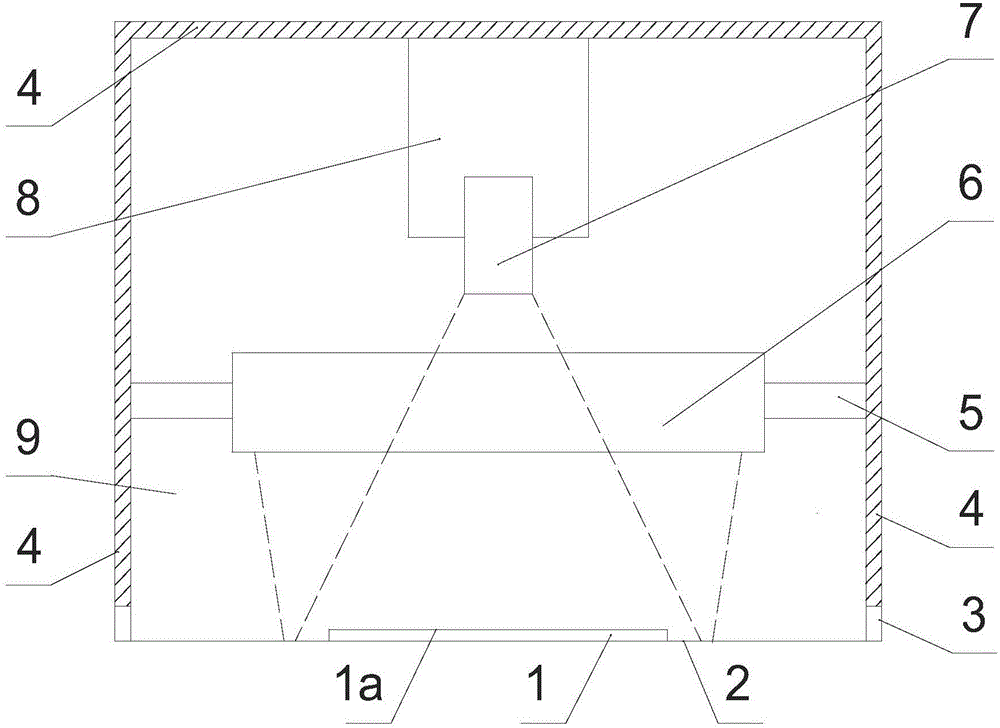
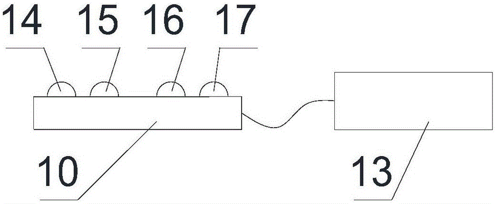
[0023] Such as Figure 1 ~ Figure 4 Shown: a machine vision LED lighting device for color recognition, including LED lighting module 6, LED drive controller 13, darkroom 9 and other parts; the LED lighting module 6 is composed of several sets of LED chipsets 10, metal Composed of heat dissipation element 11 and diffuse reflection plate 12, etc., it emits diffuse reflection white light with uniform illumination on the observation surface 1a of the tested sample 1; the LED drive controller 13 adjusts the interior of the LED lighting module 6 through the connection line 18 according to the operation instruction. The control device of the illuminance of the LED chip group 10 on the observation surface 1a; the dark room 9 refers to a device in a relatively closed space composed of a baffle plate 4 with an ambient color and a sample support plane 2 ...


PUM

PropertyMeasurementUnit
Main peak wavelengthaaaaaaaaaa

Abstract

The invention discloses a machine vision LED illuminating apparatus for color discrimination. The illuminating apparatus comprises a dark room, an LED illumination module arranged in the dark room, and an LED driving controller connected with the LED illumination module, wherein the LED illumination module is composed of a plurality of LED chip sets, a metal cooling element and a diffuser plate and emits diffuse reflection white light with uniform illuminance on an observation surface; the driving controller is a control device for adjusting the illuminance of the LED illumination module on the observation surface through a connected circuit according to an operating instruction; the dark room is a relatively closed space device composed of a front baffle, a rear baffle, a left baffle, a right baffle and an upper baffle with the ambient color and a sample supporting plane with the background color, and is provided with a sample channel used for a production line; and the LED illumination module and a vision camera are respectively fixed inside the device through different connecting pieces.

Description

technical field [0001] The invention belongs to the technical field of machine vision, in particular to a machine vision LED lighting device for color recognition. Background technique [0002] With the advancement of image recognition technology, the application of machine vision in the industrial field has become more and more extensive. Machine vision is a technology that uses machines for image acquisition and image processing, and then replaces human eyes to identify product characteristics. In the process of mass industrial production, it is inefficient for operators to inspect and classify attributes such as product surface color by eyes, and the consistency of inspection results is poor. The use of machine vision automatic detection can double the production efficiency, improve product quality, and greatly reduce labor intensity. Therefore, machine vision systems have been widely used in production lines such as product quality inspection and quality control. [0...

Claims


Application Information

Patent Timeline
IPC IPC(8): G01N21/25
CPCG01N21/255
Inventor 祁永庆
Owner SHANGHAI DIANJI UNIV
Learn More