Capacitor detection system and passive pin-separating seat module thereof
A passive capacitor technology, applied to capacitor terminals, capacitor components, instruments, etc., can solve problems such as increased leakage current, large reaction force, short circuit, etc., and achieve the effect of reducing frictional resistance and avoiding increased leakage current or short circuit
- Summary
- Abstract
- Description
- Claims
- Application Information
AI Technical Summary
Problems solved by technology
Method used
Image

Examples
no. 1 example
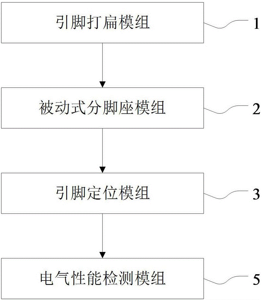
[0054] see Figure 1 to Figure 8 As shown, the first embodiment of the present invention provides a capacitor detection system S, which includes: a pin flattening module 1, a passive sub-pedestal module 2, a pin positioning module 3 and an electrical performance detection module 5, The "passive" defined by the passive sub-foot module 2 refers to: the passive sub-foot module 2 will be passively contacted by the two conductive pins P of the capacitor C to carry out the two conductive pins of the capacitor C. P's split-leg action.
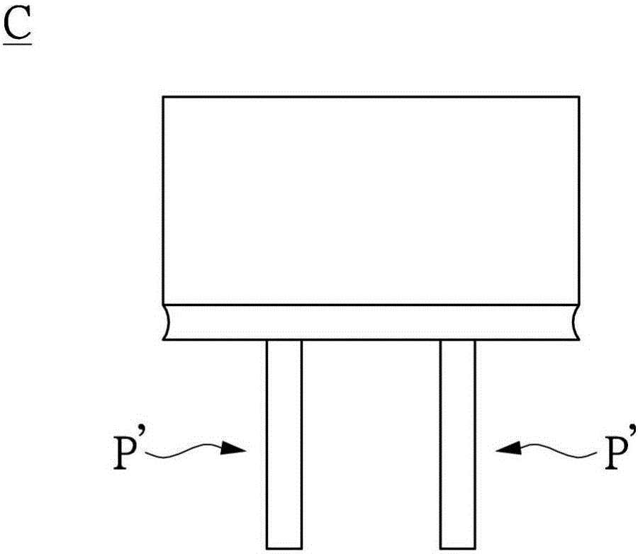
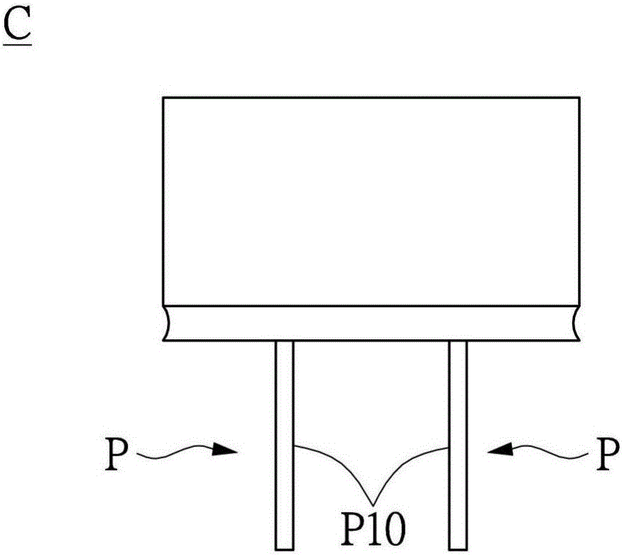
[0055] First, cooperate Figure 1 to Figure 3 As shown, the pin flattening module 1 can be used to flatten two conductive pins P' of a capacitor C, so that two cylindrical conductive pins P' are flattened into two flat conductive pins Foot P. For example, the capacitor C can be a solid electrolytic capacitor of the rolling type, figure 2 is a schematic side view showing the two conductive pins P' of the capacitor C before being flattened, image...
no. 2 example
[0062] see Figure 9 as well as Figure 10 As shown, the second embodiment of the present invention provides a passive sub-pedestal module 2, which is used to diverge or bifurcate two conductive pins P of a capacitor C from each other, and the passive sub-pin module 2 includes a base Seat structure 20 and a rotatable structure 21 . In addition, the rotatable structure 21 is rotatably disposed on the base structure 20 , and the rotatable structure 21 has an arc surface 2100 .
[0063] Furthermore, the rotatable structure 21 includes a pivot shaft 211 detachably connected between the first pivot base 2012 and the second pivot base 2022 and a pivot shaft 211 disposed between the first pivot base 2012 and the second pivot base. The pivoting ball 213 is pivotally sleeved on the pivoting shaft 211 between the sockets 2022 . In addition, the arc surface 2100 can be a spherical surface 2130 of the pivoting ball 213, and the two contact sides P10 of the two conductive pins P can sim...
no. 3 example
[0065] see Figure 11 as well as Figure 12 As shown, the third embodiment of the present invention provides a passive sub-foot module 2, which is used to diverge or bifurcate two conductive pins P of a capacitor C from each other, and the passive sub-foot module 2 includes a base Seat structure 20 and a rotatable structure 21 . In addition, the rotatable structure 21 is rotatably disposed on the base structure 20 , and the rotatable structure 21 has an arc surface 2100 .
[0066]Furthermore, the rotatable structure 21 includes a rolling ball 214 . In addition, the arc surface 2100 can be a spherical surface 2140 of the rolling ball 214, and the two contacting sides P10 of the two conductive pins P can slide and contact the spherical surface 2140 of the rolling ball 214 at the same time, so that the two conductive pins P can contact each other. Bifurcated and inclined at a predetermined angle θ with respect to the bottom end of the seat board B, and the seat board B is limi...
PUM
 Abstract
Description
Claims
Application Information