Method for forecasting rock blasting damage depth of nuclear power projects

A nuclear power engineering, deep technology, applied in the direction of blasting, electrical digital data processing, special data processing applications, etc., can solve the problems that group hole effect cannot be considered, pre-splitting blasting damage depth error, underlying bedrock damage is not large, etc. Achieve the effects of reducing the number of on-site tests, reducing the workload in the field, and improving construction efficiency

Active Publication Date: 2017-01-11
INST OF ROCK AND SOIL MECHANICS - CHINESE ACAD OF SCI
View PDF3 Cites 32 Cited by
  • Summary
  • Abstract
  • Description
  • Claims
  • Application Information

AI Technical Summary

Problems solved by technology

Numerical simulation can conveniently, economically and quickly simulate the attenuation law and damage characteristics of the site under the conditions of different blasting scales, maximum charge volumes, and excavation depths, and can make up for the shortcomings of insufficient field acoustic wave test data. When determining the input load of the model explosion, the single-hole single-segment simplified treatment is performed, that is, it is assumed that all the blasting charges in the field blasting are concentrated in one blasting hole for one-time detonation, and the effect of group holes cannot be considered. The actual situation is quite different
[0004] In addition, because pre-splitting blasting needs multiple holes to detonate simultaneously to obtain a better pre-splitting effect, the vibration generated is relatively large, but the actual damage to the underlying bedrock is not large, which is significantly different from step blasting. Therefore, the existing method adopts step-based blasting. The damage depth established by the method and the change law of particle vibration velocity to predict the damage depth of pre-splitting blasting will produce very large errors

Method used


Image

  • Method for forecasting rock blasting damage depth of nuclear power projects
  • Method for forecasting rock blasting damage depth of nuclear power projects
  • Method for forecasting rock blasting damage depth of nuclear power projects

Examples


Embodiment 1

[0046] Example 1, such as figure 1 As shown, a method for predicting the blasting damage depth of rock mass in nuclear power engineering involves the following steps for the two blasting methods of step blasting and pre-splitting blasting:

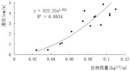
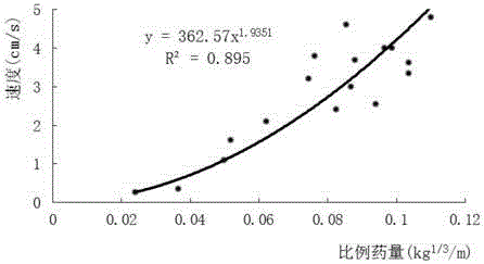
[0047] Step 1. Carry out blasting vibration tests on the site for blasting shots with a maximum charge range of 8-40kg, among which the number of blasting shots is 34; obtain the peak particle vibration velocity at different distances from the blast source for each shot The actual measured value, and then use the Sadowski formula for regression analysis to obtain the attenuation law of blasting vibration on the site.

[0048] For each blasting, arrange more than three measuring points at different distances from the blasting source in the area behind the blasting throwing direction (the distance of the blasting source at one of the measuring points is 40 meters), and arrange a measuring point at each place, and arrange a measuring point at...


PUM


Abstract

The invention relates to a method for forecasting rock blasting damage depth of nuclear power projects. The method comprises the following steps of performing the blasting vibration testing to determine a site vibration attenuation rule; performing the sound wave testing to primarily determine the rock damage depth; performing the finite element numerical simulation, and calculating the rock particle vibration speed and rock blasting damage depth; respectively establishing the change rules of the particle peak vibration speed (1m away from a blasting source R) along with the rock blasting damage depth under the step blasting and pre-fracturing blasting types; substituting the explosive charging quantity Q0 of an actual section into the site blasting vibration attenuation rule and the change rules of the particle peak vibration speed along with the rock blasting damage depth, so as to forecast the blasting damage depth caused by the explosive charging quantity. The method has the characteristics that one part of site sound wave testing can be replaced with the numerical simulation, the site testing frequency is reduced, the field workload is reduced, and the construction efficiency is improved; the site blasting group hole effect is comprehensively considered, the forecasting is accurate, and the operation is convenient and rapid.

Description

technical field [0001] The invention relates to a method for predicting the blasting damage depth of rock mass in nuclear power engineering. Background technique [0002] Nuclear power plants generally choose relatively complete rock mass as the foundation of key buildings such as the nuclear island to meet the deformation requirements of the main building of the nuclear power plant under the action of its own weight and seismic load. Since nuclear power projects have high requirements on the integrity of the foundation surface, how to predict the extent of damage to the retained bedrock by blasting excavation is a prerequisite to ensure the integrity of the foundation surface and thus ensure the safe construction of nuclear power projects. [0003] At present, in the fields of water conservancy, hydropower and geotechnical engineering, the relationship between the peak vibration velocity of particles at a certain distance from the explosion source and the damage depth of ro...

Claims


Application Information

Patent Timeline
Patent Type & Authority Applications(China)
IPC IPC(8): G06F17/50F42D1/00F42D3/04
CPCF42D1/00F42D3/04G06F30/13G06F30/20G06F30/23
Inventor 李海波刘亚群夏祥刘博于崇李俊如周青春罗超文
Owner INST OF ROCK AND SOIL MECHANICS - CHINESE ACAD OF SCI
Why Eureka
Try Eureka