Operation method of electric peeling device for protective cores of waste cables

A technology of waste cables and operation methods, which is applied in the direction of cable installation, cable installation devices, equipment for dismantling/armouring cables, etc., can solve the problems of high cost of cable insulation packaging and recycling, scrapping of cable conductors, and reduction of recycling prices, etc., to achieve The peeling effect is good, the quality is guaranteed, and the effect of reducing economic losses

Active Publication Date: 2017-01-11
HUATONG CABLE INC
View PDF7 Cites 33 Cited by
  • Summary
  • Abstract
  • Description
  • Claims
  • Application Information

AI Technical Summary

Problems solved by technology

[0002] In the production process of wire and cable enterprises, there will inevitably be some cable products that do not meet the process requirements, and long-term extrusion of such cables will cause great disadvantages to the company's capital occupancy rate, warehouse environment, etc. impact; for this type of product, the traditional solution is to manually divide the cable into short sections of several meters long, and then use a stripping tool to manually separate the insulation or use an old-fashioned insulation stripper to squeeze the cable insulation layer under the extrusion of the gear. break apart, and then scrap the cable conductors
Under the traditional stripping method, when the medium and high voltage power cables have the characteristics of thick insulation layer, difficult to peel off, and difficult to cut, it is more time-consuming, laborious, low in efficiency, high in labor costs, and the cost of packaging and recycling after the cable insulation is broken is high. The short section of insulating material is polluted after being in contact with the ground, which greatly reduces the recycling price, and all cable conductors are scrapped, which has caused great economic losses to the enterprise.

Method used


Image

  • Operation method of electric peeling device for protective cores of waste cables
  • Operation method of electric peeling device for protective cores of waste cables
  • Operation method of electric peeling device for protective cores of waste cables

Examples


Embodiment 1

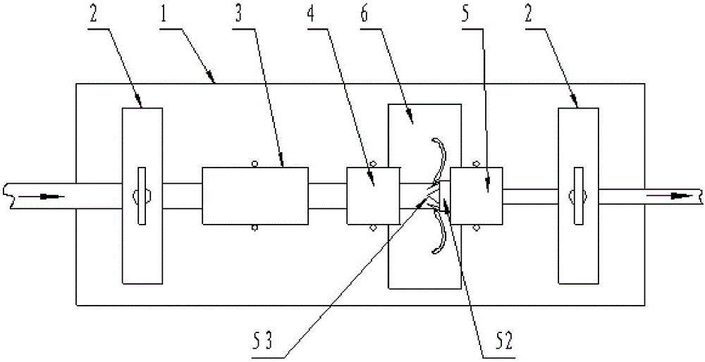
[0030] The two ends of the console 1 are provided with clamping mechanisms 2, and between the two clamping mechanisms 2, a heater 3, a skin-cutting mechanism 4, a skin-removing mechanism 5, a skin-cutting mechanism 4 and a skin-removing mechanism 5 are sequentially arranged between the two clamping mechanisms 2 along the running direction of the cable An insulating layer collection hole 6 is arranged between them;

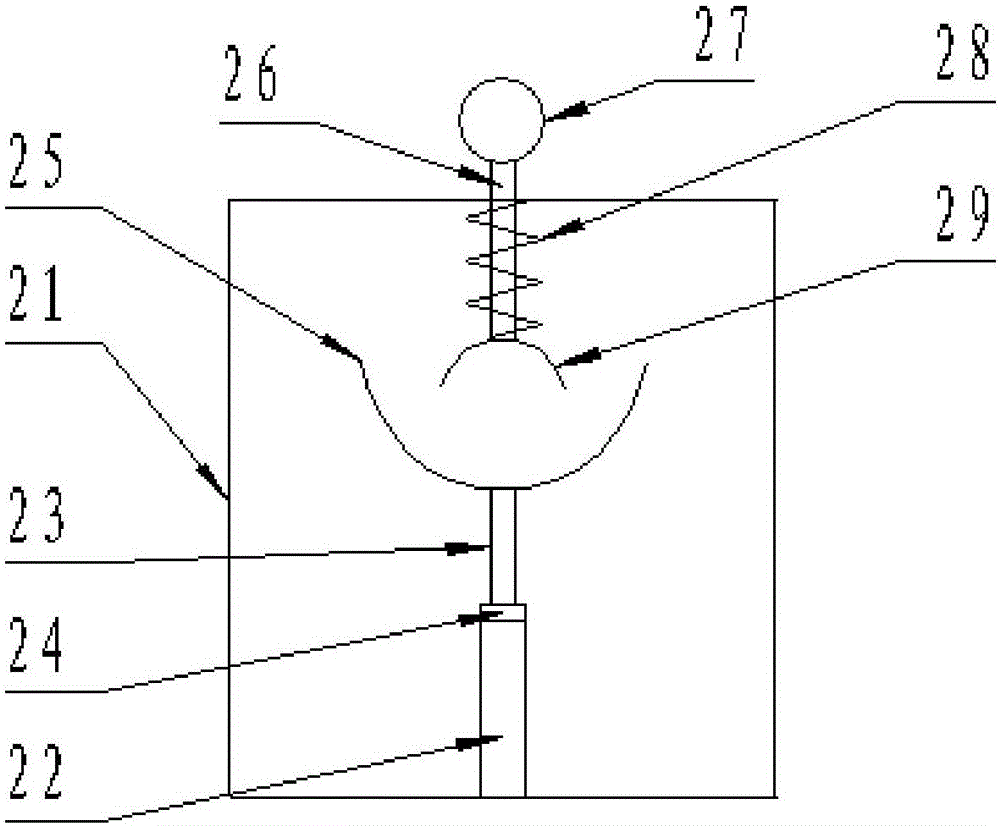
[0031] The structure of the clamping mechanism 2 is as follows: the main rod 22 is arranged in the lower middle part of the fixed frame 21, the telescopic rod 23 is arranged in the main rod 22, the outer periphery of the telescopic rod 23 above the main rod 22 is provided with a locking ring 24, and the upper end of the telescopic rod 23 is provided with a lower clip. Sheet 25, connecting rod 26 is set in the reserved hole of fixed frame 21 top center, and connecting rod 26 upper end is provided with draw ring 27, and lower end is provided with upper clip 29, and co...


PUM


Abstract

Provided is an operation method of an electric peeling device for the protective cores of waste cable. Clamping mechanisms are arranged at the two ends on an operation table. A heater, a cutting mechanism and a stripping mechanism are sequentially arranged along the running direction of cables between the two clamping mechanisms. An insulating layer collection hole is arranged between the cutting mechanism and the stripping mechanism. The operation method comprises the following steps: adjusting the height of the telescopic rods on the clamping mechanisms; adjusting the distance between the blade of a cutter on the cutting mechanism and the inner core of a cable and the distance between the blade of a separator on the stripping mechanism and the inner core of the cable; adjusting the centers of the mechanisms to the same axis line; and heating, cutting and stripping the insulating layer of a to-be-processed cable in sequence. The device has a simple structure. The operation method is simple. The use effect is good. Operation by workers is facilitated. The labor intensity of workers is reduced greatly. The stripping effect is good, and the production efficiency is high. The method is suitable for stripping the rubber sheaths of all kinds of cables. High cable core recovery efficiency is achieved.

Description

technical field [0001] The invention relates to stripping equipment for waste and old cable insulation layers, in particular to an operating method for an electric stripping device for protecting cores of waste and old cables. Background technique [0002] In the production process of wire and cable enterprises, there will inevitably be some cable products that do not meet the process requirements, and long-term extrusion of such cables will cause great disadvantages to the company's capital occupancy rate, warehouse environment, etc. impact; for this type of product, the traditional solution is to manually divide the cable into short sections of several meters long, and then use a stripping tool to manually separate the insulation or use an old-fashioned insulation stripper to squeeze the cable insulation layer under the extrusion of the gear. Break and separate, and then scrap the cable conductor. Under the traditional stripping method, medium and high voltage power cable...

Claims


Application Information

Patent Timeline
Patent Type & Authority Applications(China)
IPC IPC(8): H02G1/12
CPCH02G1/1265H02G1/1275
Inventor 史海宝史科伟张漫坡
Owner HUATONG CABLE INC
Why Eureka
Try Eureka