A Piezoelectric-Magnetoelectric Composite Microgenerator

A magnetoelectric composite and generator technology, applied in piezoelectric effect/electrostrictive or magnetostrictive motors, generators/motors, asynchronous induction motors, etc., can solve low conversion efficiency, long activation time and complex structure and other issues, to achieve the effect of improving the axial impact resistance, improving the impact resistance, and improving the impact resistance

Active Publication Date: 2018-10-30
BEIJING INSTITUTE OF TECHNOLOGYGY
View PDF5 Cites 0 Cited by
  • Summary
  • Abstract
  • Description
  • Claims
  • Application Information

AI Technical Summary

Problems solved by technology

At present, such micro-generators at home and abroad all use magnet yoke rotation, such as the axial-flow pneumatic micro-turbine power generation system designed by Imperial College London, the variable reluctance micro-generator designed by the University of California, Berkeley, and the French LEG The planar micro-generator designed by the research team of the United States, the micro-generator co-designed by the Georgia Institute of Technology and the Massachusetts Institute of Technology, this type of micro-generator is large in size, complex in structure, low in conversion efficiency, and long in activation time
In addition, in some environments that need to be sealed, the ambient energy cannot be obtained through wind turbines, and this type of generator cannot work

Method used


Image

  • A Piezoelectric-Magnetoelectric Composite Microgenerator
  • A Piezoelectric-Magnetoelectric Composite Microgenerator
  • A Piezoelectric-Magnetoelectric Composite Microgenerator

Examples


Embodiment Construction

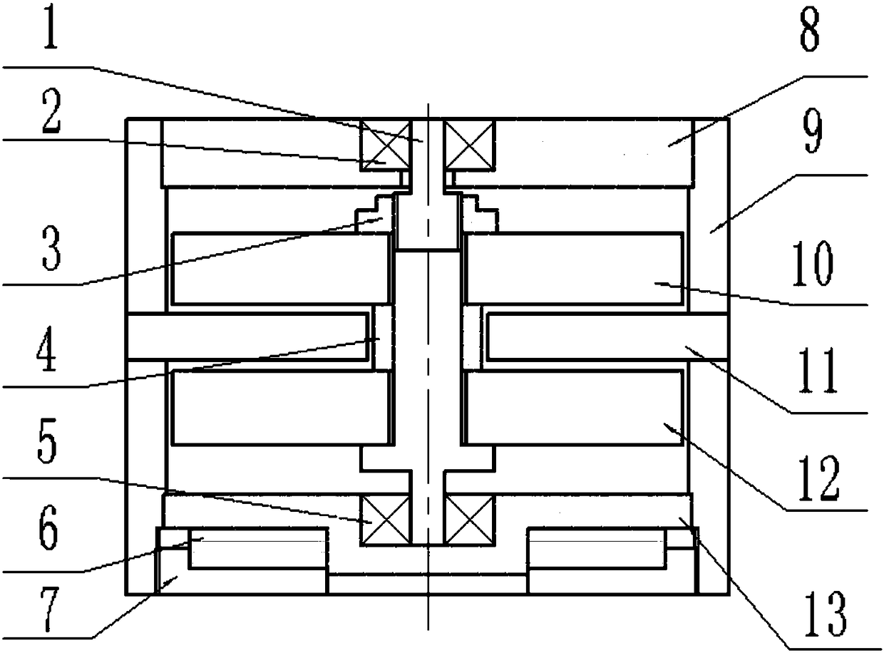
[0031] The present invention will be described in detail below with reference to the accompanying drawings and examples.

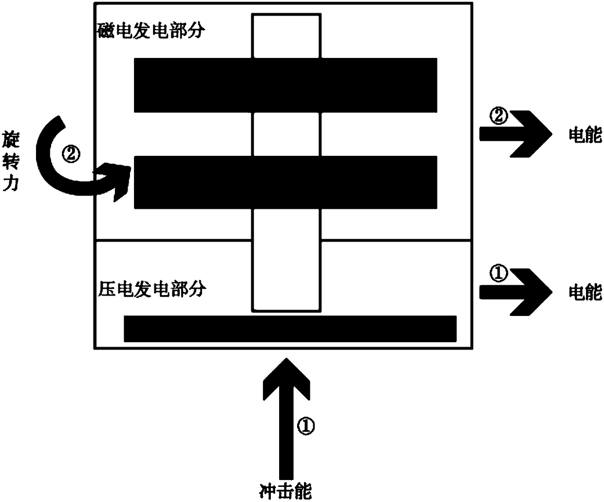
[0032] This embodiment provides a piezoelectric-magnetoelectric composite micro-generator, the micro-generator is composed of a piezoelectric part and a magnetoelectric part, and its working principle is as follows figure 1 shown.

[0033] Among them, the piezoelectric micro-generator part adopts a piezoelectric stack structure composed of multi-layer piezoelectric materials. Piezoelectric generators have fast activation properties and thus have the advantage of short activation times. The power source is the external axial impact force, which is converted into electrical energy through the piezoelectric effect of the piezoelectric stack.

[0034] The magnetoelectric generator part adopts the structure of the disc permanent magnet micro generator. Compared with other micro-generators, the disc-type permanent magnet micro-generator has the advantages of ...


PUM


Abstract

The invention discloses a piezoelectric-magnetoelectric compound micro-generator, which is mainly composed of two parts: a piezoelectric power generation part and a magnetoelectric power generation part. The magnetoelectric part adopts a single rotor plate type permanent magnet micro-generator structure; the piezoelectric part adopts a piezoelectric stack structure. Both parts share the same cylindrical generator housing. The piezoelectric part comprises a piezoelectric stack and a top screw. The top screw is fixedly arranged at the lower end of the generator housing and below the lower cover of the magnetoelectric part. The piezoelectric stack is mounted in the space formed between the top screw and the lower cover. When the micro-generator feels the impact environmental force, the piezoelectric power generation part begins to work. When the micro-generator feels the rotary inertia force, the magnetoelectric power generation part begins to work. According to the invention, the piezoelectric-magnetoelectric compound micro-generator adopts a compound power generation mode and in terms of the magnetoelectric power generation part, a rotary inertia force power generation mode is adopted. Simple in structure and small sized, the power density is large; the ability to withstand impact is increased; the time to activate the generator is shortened; the environmental force is fully utilized; and the generator can be used in a sealed environment.

Description

technical field [0001] The invention relates to a piezoelectric-magnetoelectric composite micro-generator, in particular to an impact-type piezoelectric and axial magnetic field magnetoelectric composite micro-generator, which belongs to the technical field of energy development. Background technique [0002] In recent years, micro-mechanical and electrical systems have developed rapidly, and the reduction in the volume of electromechanical systems requires the miniaturization of energy supply devices. Micro energy devices can be divided into two categories: micro chemical batteries and micro generators. The current main problem of micro-chemical batteries is that they carry limited energy, need to replenish energy regularly, and have poor self-sustaining power. The micro generator can actively obtain energy from the environment, which is a self-transducer, does not need to replenish energy regularly, and at the same time has no pollution itself, so it has a good developmen...

Claims


Application Information

Patent Timeline
Patent Type & Authority Patents(China)
IPC IPC(8): H02N2/18H02K17/42
CPCH02K17/42H02N2/183
Inventor 代俊隋丽张力丹张美云石庚辰牛少华王彭颖恺洪扬黄珏
Owner BEIJING INSTITUTE OF TECHNOLOGYGY
Why Eureka
Try Eureka