Ultrasonic atomization deacidification dedusting system

A dust removal system, ultrasonic technology, applied in the direction of chemical instruments and methods, separation methods, dispersed particle separation, etc., can solve the problems of short service life, entering the smoke chamber, long-term intrusion, etc., to prevent precipitation and prolong service life Effect

Inactive Publication Date: 2017-01-18
YICHANG JIUTIAN ENVIRONMENTAL SCI & TECH
View PDF11 Cites 5 Cited by
  • Summary
  • Abstract
  • Description
  • Claims
  • Application Information

AI Technical Summary

Problems solved by technology

[0003] Generally, the ultrasonic atomization deacidification and dedusting system includes: the lye configuration device uses an ultrasonic atomization deacidification and dust removal tower, and a mechanical stirrer is installed in the lye configuration device to mix lime powder and water evenly; The dedusting tower includes a tower body. The upper part of the tower inner chamber is a smoke inlet chamber, and the lower part is a deacidification reaction chamber. The bottom of the deacidification reaction chamber is a lye pool. Although the lye configuration device in the device has obtained evenly mixed lye, and the ultrasonic atomization deacidification and dedusting tower has also realized the deacidification of smoke, the disadvantages that still exist in this device are: 1) the lye configuration device uses The mechanical stirrer needs to penetrate into the lye for a long time, so its service life is extremely short; 2) In order to make the alkali mist in the deacidification reaction chamber thicker, it should prevent the alkali mist from entering the smoke chamber from the smoke inlet pipe, but generally The smoke inlet pipe is only a through pipe. If the air pressure in the deacidification reaction chamber is greater than the air pressure in the smoke inlet chamber, the alkali mist will enter the smoke inlet chamber from the smoke inlet pipe.

Method used


Image

  • Ultrasonic atomization deacidification dedusting system
  • Ultrasonic atomization deacidification dedusting system
  • Ultrasonic atomization deacidification dedusting system

Examples


Embodiment Construction

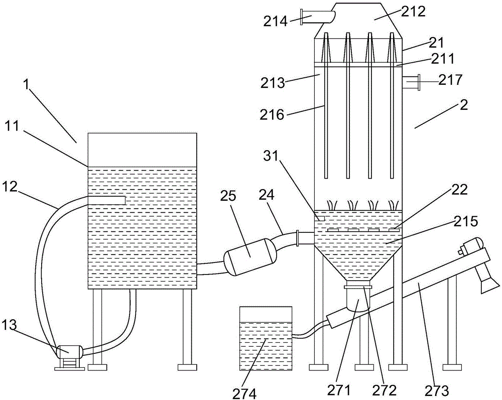
[0017] Such as figure 1 As shown, the present invention proposes an ultrasonic atomization deacidification and dust removal system, comprising a lye disposing device 1, and the lye disposing device 1 comprises: a dispensing barrel 11 for containing lye; 11 is connected to the bottom, and its other end is connected to the middle part of the configuration barrel 11; and the liquid return pump 13 is arranged on the liquid return pipeline 12, and its liquid inlet is connected to the bottom of the configuration barrel 11 through the liquid return pipeline 12, and its liquid outlet passes through The liquid return pipeline 12 communicates with the middle part of the configuration barrel 11 to circulate the lye in the configuration barrel 11.

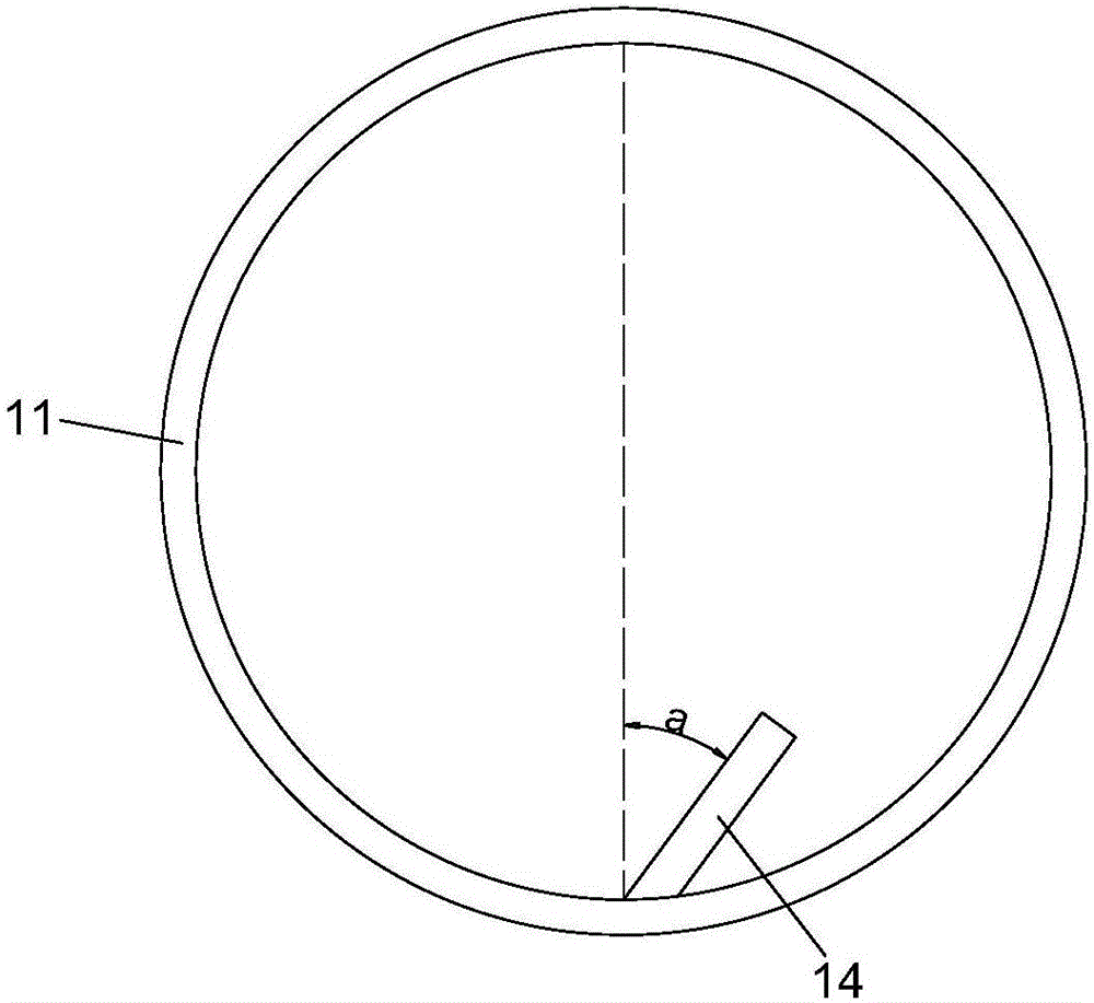
[0018] Such as figure 2 As shown, in order to form a vortex in the configuration barrel 11 after the return liquid pipeline 12 returns liquid, so that the lye is mixed more evenly during rotation, the configuration barrel 11 is a cylindrical...


PUM


Abstract

The invention provides an ultrasonic atomization deacidification dedusting system, which comprises an alkali lye preparation device. The alkali lye preparation device comprises a preparation barrel for containing alkali lye, a liquid return pipeline with one end communicated with the bottom of the preparation barrel and the other end communicated with the middle part of the preparation barrel, and a liquid return pump which is arranged on the liquid return pipeline. A liquid inlet of the liquid return pump is communicated with the bottom of the preparation barrel through the liquid return pipeline, and a liquid outlet of the liquid return pump is communicated with the middle part of the preparation barrel through the liquid return pipeline. Thus, alkali lye in the preparation barrel is circulated. The invention has the following beneficial effects: the liquid return pipeline and the liquid return pump are used to replace a mechanical agitator, and service time of the liquid return pipeline and the liquid return pump is long such that service life of the ultrasonic atomization deacidification dedusting system is prolonged.

Description

technical field [0001] The invention relates to domestic waste incineration equipment, in particular to an ultrasonic atomization deacidification and dust removal system. Background technique [0002] In the prior art, in order to incinerate domestic waste, domestic waste incineration equipment is used. The domestic waste incineration equipment includes: a pyrolysis gasifier for incinerating domestic waste; a waste heat boiler connected to the pyrolysis gasifier; The flue gas produced by the gasifier is input into the waste heat boiler to process the temperature of the flue gas; the ultrasonic atomization deacidification and dust removal system connected with the waste heat boiler is used to deacidify the flue gas; and the ultrasonic atomization deacidification and dust removal system is connected A connected bag filter to remove dust from the flue gas. [0003] Generally, the ultrasonic atomization deacidification and dedusting system includes: the lye configuration device...

Claims


Application Information

Patent Timeline
Patent Type & Authority Applications(China)
IPC IPC(8): B01D53/78B01D53/40B01D47/06
CPCB01D47/06B01D53/40B01D53/78B01D2259/124B01D2258/0291
Inventor 郭光玉李志斌樊孝凯周广平郭群超唐才褔
Owner YICHANG JIUTIAN ENVIRONMENTAL SCI & TECH
Why Eureka
Try Eureka